
Uma viga I ou viga H não é uma barra redonda com diâmetro maior. Seus dois banzos e alma formam uma seção aberta cuja rigidez muda de acordo com a direção. Soldagem, corte, manuseio e fabricação podem criar distorção angular do flange, curvatura longitudinal, varredura lateral, torção ou deformação local da teia. Cada erro precisa de um dado diferente, caminho de carga e método de correção.
Uma máquina endireitadora de vigas I eficaz deve responder a cinco perguntas antes de o equipamento ser selecionado:
- A peça de trabalho é uma seção laminada, uma viga construída soldada, uma viga cônica, uma seção em T ou um conjunto fabricado com acessórios?
- É a distorção angular do flange de erro controlado, curvatura, varrer, torção, ondulação da web ou uma combinação?
- Onde podem os rolos, suporta e pressiona o contato da ferramenta sem esmagar a alma, marcar uma superfície acabada ou carregar uma zona de solda sensível?
- A correção necessária pertence a um endireitador de flange contínuo, uma estação de pressão pontual, um sistema de torção/curvatura ou uma rota de revisão de engenharia?
- How will the fully released beam be remeasured and accepted under the customer's drawing and applicable fabrication procedure?

*Ilustração do conceito de engenharia de uma viga H soldada em uma célula contínua de endireitamento de flange. Não é uma fotografia do site do cliente ou uma declaração de desempenho. Rolos reais, guias, faixa de seção, os limites de força e aceitação exigem a família de feixes controlados e testes de amostras representativas.*
Definir a família de vigas e o estágio de produção
| Família de peças | Principal diferença | Rota necessária |
|---|---|---|
| Laminado a quente eu- ou seção H | A geometria vem do moinho; distorção pode surgir durante o manuseio ou fabricação posterior | Confirme a condição do moinho, propriedades da seção e correção a frio permitida |
| Viga H soldada | As placas da alma e do flange são unidas por soldas longitudinais; a distorção angular do flange é um erro comum pós-soldagem | Medição específica do flange e correção contínua ou escalonada |
| Viga em T | Um flange e uma alma criam um caminho de carga assimétrico | Suporte dedicado e layout de guia |
| Viga cônica ou de profundidade variável | A profundidade e a rigidez da banda mudam ao longo do comprimento | A receita e a posição do ferramental devem seguir o mapa da seção |
| Seção I/H assimétrica | Flanges desiguais ou alma deslocada alteram o eixo neutro e o retorno elástico | Validação separada de família e amostra |
| Viga com reforços, placas finais ou suportes | Os acessórios interrompem as zonas de contato e podem bloquear a distorção | Manuseio com reconhecimento de recursos e revisão de engenharia local |
| Galvanizado, viga pintada ou revestida | Marcas de contato e danos no revestimento tornam-se itens aceitos | Almofadas/rolos qualificados e inspeção de superfície pós-processo |
| Membro estrutural instalado ou danificado pelo serviço | Cargas, rachaduras e histórico de conexão podem ser desconhecidos | Engenharia estrutural e rota de inspeção, não é uma receita de produção |
Esta página se concentra no endireitamento controlado no chão de fábrica de componentes de vigas laminadas ou soldadas antes da liberação final. Não autoriza correção de campo de estrutura em serviço.
Separe os modos de distorção
Distorção Angular de Flange
A soldagem longitudinal pode girar ou inclinar as bordas do flange em relação à alma. Um endireitador de flange dedicado utiliza uma carga de rolo controlada contra o flange enquanto guia a viga através da máquina. Stierli-Bieger descreve correção hidráulica de rolos em operação contínua para vigas soldadas; Corimpex descreve sistemas horizontais que corrigem os flanges de vigas H soldadas como parte de uma linha de soldagem.
This is not the same as correcting the full beam's longitudinal centerline.
Cambagem Longitudinal
Camber is curvature in the beam's strong-axis plane. Pode ser intencional ou não intencional. O desenho deve distinguir a curvatura projetada da distorção antes de qualquer comando de correção ser emitido.
Varredura Lateral
Varredura é a curvatura no plano do eixo fraco. Necessita de um suporte e direção de carga diferentes da curvatura, e a estreita relação alma/flange pode tornar a seção sensível à instabilidade local.
Torção
Twist é a rotação da seção ao longo de seu comprimento. Uma passagem de roletes apenas com flange pode deixar a torção inalterada ou redistribuí-la. Twist precisa de medições de seção indexadas e uma rota de torção controlada.
Ondulação da Web, Deformação ou dano local
A deformação local da alma não é automaticamente uma entrada da máquina de endireitamento. Flambagem de teia fina, amassados, rachaduras, defeitos de solda e danos afetados pelo calor exigem inspeção e disposição de engenharia antes que a força seja aplicada.
| Resultado observado | Possível causa | Rota |
|---|---|---|
| Ambas as bordas do flange mostram um erro angular consistente após a soldagem | Encolhimento da solda e rotação do flange | Candidato para endireitamento de rolo de flange dedicado |
| A linha central do feixe se curva verticalmente, mas o ângulo da seção permanece estável | Curvatura ou arco de eixo forte | Pressão medida ou rota de curvatura |
| O feixe se curva lateralmente | Varredura ou arco de eixo fraco | Suporte lateral e rota de correção |
| O ângulo da seção transversal gira ao longo do comprimento | Torção | Medição de torção e correção de torção dedicada |
| Mudança curta e brusca perto de um acessório ou parada de solda | Restrição local, entrada de calor, dano ou erro de fabricação | Inspecionar e encaminhar para a engenharia; não calcule a média na curvatura global |
| A teia mostra ondas enquanto os flanges permanecem alinhados | Instabilidade local da alma ou encolhimento da solda | Rota de engenharia específica da Web; endireitador de flange pode não resolver |
| A forma medida muda quando as posições de suporte se movem | Afundamento intenso da viga ou dado instável | Congelar o suporte e a condição de medição, então repita |
Estabeleça uma cadeia de referência específica para feixe
Uma viga longa e pesada pode ceder nos transportadores e assentar de maneira diferente em rolos desgastados ou desiguais. O plano de inspeção deve definir:
- orientação do feixe e origem axial;
- flange de referência, plano central da web e seção final;
- contagem de apoio, espaçamento, altura e balanço do rolo;
- se o resultado é estado livre, suporte controlado ou referenciado por fixação;
- perfis de curvatura e varredura de comprimento total;
- rotação ou torção da seção em estações axiais controladas;
- ângulo flange-teia em ambos os lados;
- largura da flange, grossura, planicidade e condição da borda;
- profundidade da web, grossura, planicidade e ondulação local;
- localização da solda, condição da ponta da solda e zonas de medição excluídas;
- repetibilidade após descarregamento, invertendo ou girando o feixe;
- correlation with the customer's fixtures, medidores e definição de desenho.

*Ilustração do conceito de engenharia de medições separadas de comprimento total e de seção transversal. Não é um layout de medidor prescrito. Posições reais do sensor, os cálculos de espaçamento e aceitação do suporte exigem a correlação do desenho e da bitola do cliente.*
Proteja a Web, Soldas e superfícies acabadas
Zonas padrão protegidas ou de revisão
- áreas de banda fina não suportadas sob uma carga de prensa concentrada;
- soldar dedos, início/parada de soldagem e indicações de solda não inspecionada;
- bordas de flange que definem uma interface acabada;
- furos de parafusos, slots, lidas e recortes;
- reforços, colchetes, placas finais e detalhes de conexão;
- marcas de identificação e etiquetas de rastreabilidade;
- galvanizado, superfícies pintadas ou expostas arquitetonicamente sem almofadas de contato qualificadas;
- amassados, rachaduras, laminações, goivas, corrosão severa ou zonas de reparo anteriores.
Zonas de contato potencialmente aprovadas
- terrenos de flange largos identificados pelo desenho de seção controlada;
- zonas reforçadas de transferência de carga de alma/flange suportadas contra flambagem local;
- perfis de rolos substituíveis correspondentes à geometria do flange e da alma;
- limpe superfícies não revestidas antes do acabamento final quando o plano de processo permitir;
- handling points verified for the beam's mass, centro de gravidade e layout do acessório.
O mapa de contato deve ser controlado por revisão por família de seção. Uma posição do rolete adequada para uma viga H com flange paralelo pode interferir com um flange cônico, reforço ou seção assimétrica.
Selecione o método de correção no mapa de erros
Endireitamento Contínuo de Rolo de Flange
Este método é apropriado quando o problema controlado é a distorção angular repetível do flange ao longo de uma viga fabricada por solda.. Stierli-Bieger descreve um ou mais passes com rolos ajustados à peça e correção necessária. Corimpex descreve sistemas alimentados horizontalmente com grupos de correção posicionados independentemente. Uma solução de produção ainda precisa definir:
- orientação da viga suportada;
- perfis de rolo e folgas para cada faixa de flange e alma;
- posições de guia e controle anti-torção;
- sequência de passagem e configuração de rolo limitada;
- altura e sincronização do transportador de entrada/saída;
- soldar, proteção de superfícies e bordas;
- verificação de ângulo de flange liberado e feixe completo.
Correção Point-Press para Camber ou Sweep
Uma prensa hidráulica pode resolver um erro de linha central global ou local medido quando os suportes e o ponto de prensagem formam um caminho de carga seguro. Requer ferramentas amplas, estabilidade do feixe, limites de força/deslocamento, controle de retorno elástico e nova medição totalmente liberada. Uma carga concentrada não deve ser colocada sobre uma alma fina sem suporte simplesmente porque é geometricamente conveniente.
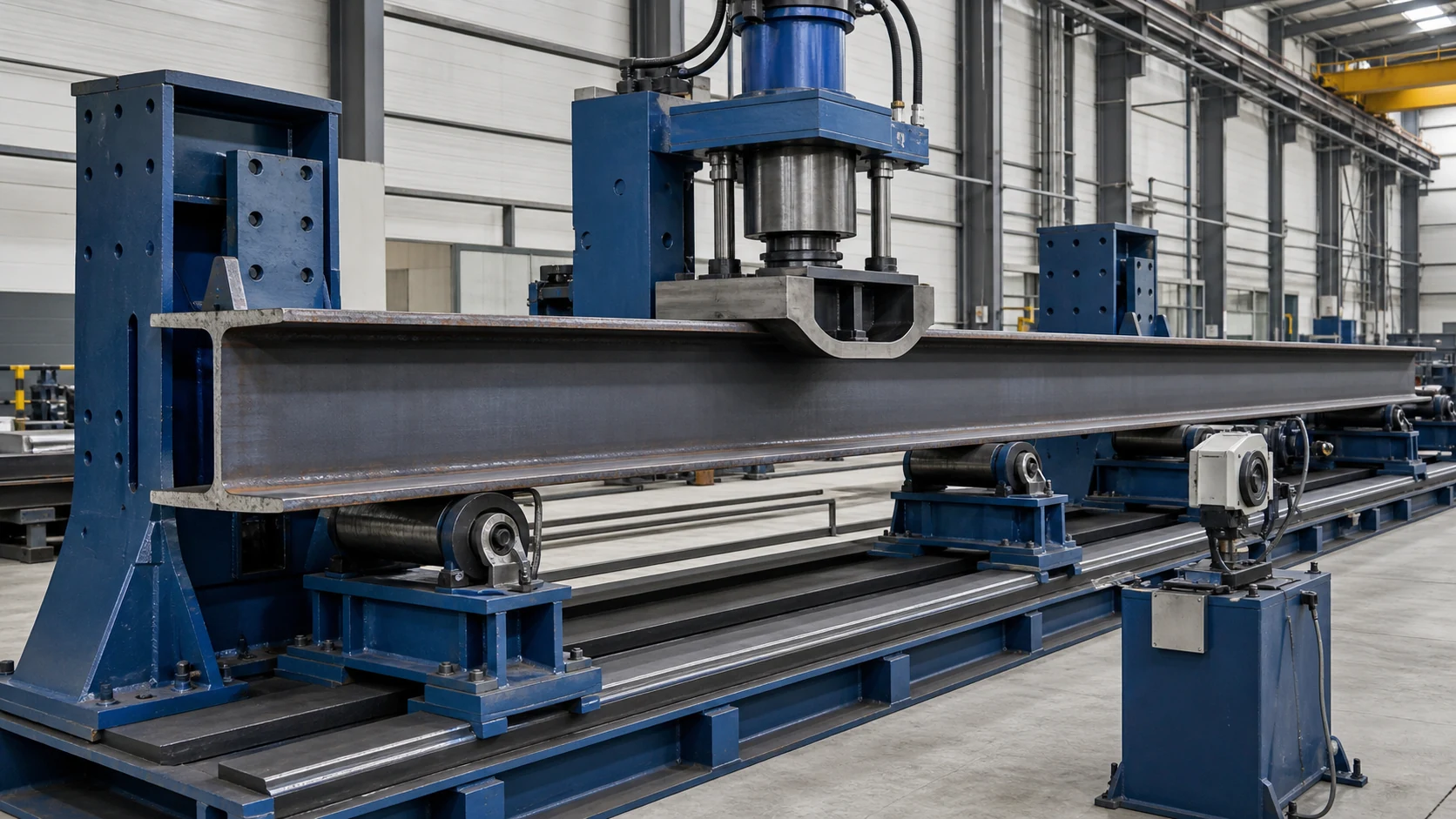
*Ilustração do conceito de engenharia de uma estação de prensa de feixe longo. Não é um caso de carga universal. Extensão de suporte, ferramentas, estresse local, resistência à flambagem, O retorno elástico e a condição da superfície exigem validação de amostra e aprovação de engenharia.*
Correção de torção ou multieixos
Quando a rotação da seção varia ao longo do comprimento, a máquina precisa de pontos de reação controlados e aplicação de torque. Ângulo do flange, curvatura, varredura e torção devem ser verificadas novamente após cada correção porque uma operação pode mover outro componente de erro.
Alisamento térmico
O endireitamento térmico é um processo de fabricação controlado separado. Requer um procedimento aprovado, revisão de material e solda, controle de temperatura e pessoal qualificado. Esta página não trata o aquecimento descontrolado da tocha como um substituto para um processo de endireitamento mecânico medido.
Ler endireitamento de prensa vs endireitamento de rolo para a comparação geral do método, em seguida, aplique as verificações de caminho de carga e instabilidade específicas da viga acima.
Integrar Medição, Manuseio e Segurança
Vigas longas e pesadas tornam o manuseio de materiais parte do sistema de endireitamento, e não um acessório. Uma célula de produção pode exigir:
- transportadores de rolos motorizados de entrada e saída;
- transporte sincronizado através da zona de correção;
- guias laterais que estabilizam sem travar em um dado falso;
- elevação, equipamento de giro ou rotação de 180 graus quando ambos os lados necessitam de acesso;
- elevação ajustável do rolo para mudanças de seção;
- detecção de presença final e lateral;
- zonas seguras em torno das extremidades móveis do feixe e dos pontos de esmagamento;
- intertravamentos de receita para família de seção e orientação;
- rastreabilidade de entrada, medições intermediárias e liberadas.
A Bendmak posiciona publicamente o endireitamento do perfil H antes ou depois da fabricação quando os flanges ou a alma estão empenados. Corimpex integra um endireitador de viga horizontal com soldagem, equipamento de montagem e rotação de feixe. Esses exemplos de mercado suportam uma arquitetura de linha integrada; eles não estabelecem a capacidade ou precisão de uma célula StraighteningTech proposta.
Construa uma porta de inspeção em torno do endireitamento
Antes da correção, confirmar:
- designação de seção, certificado de material e histórico de calor ou fabricação;
- revisão de desenho e curvatura ou conicidade intencional;
- status da solda e disposição de inspeção visual ou não destrutiva necessária;
- anexo, mapa de furos e recortes;
- condição da superfície/revestimento e zonas de contato permitidas;
- ângulo do flange de entrada, curvatura, varrer, mapa de torção e defeito local;
- elegibilidade para correção e condições de rejeição/revisão de engenharia.
Após correção, repita a inspeção dimensional controlada e quaisquer verificações de solda ou superfície necessárias. O endireitamento não pode reparar uma rachadura, solda inaceitável, laminação, buraco rasgado, fivela local grave ou seção perdida.
The governing tolerance should come from the customer's drawing and applicable fabrication or product standard. Do not copy a machine supplier's sample range into a project acceptance specification.
Demonstração externa de endireitamento de viga H
O vídeo externo a seguir mostra uma máquina endireitadora de flange de viga H. Está incluído para ilustrar a categoria do equipamento, não como um caso de cliente da StraighteningTech, especificação da máquina ou prova de aceitação.
Informações necessárias para uma proposta técnica
| Entrada | Detalhe mínimo |
|---|---|
| Família de feixe | Laminado ou soldado; EU, H, T, cônico, montagem assimétrica ou fabricada |
| Faixa de seção | Comprimento total, largura/espessura do flange, altura/espessura e massa da teia |
| Material e palco | Nota, condição de calor, processo de soldagem, antes/depois da fabricação e estado do revestimento |
| Modos de erro | Ângulo do flange, curvatura, varrer, torção, ondulação da web e mapa de defeitos locais |
| Resultado obrigatório | Tolerância de desenho, dado, condição de suporte, estações e método de inspeção |
| Recursos protegidos | Soldas, buracos, lida, reforços, placas finais, revestimentos e interfaces acabadas |
| Manuseio | Método de carregamento, orientação, centro de gravidade, altura do transportador e requisitos de giro |
| Necessidade de produção | Mistura de produtos, vencer o alvo, mudança, automação e rastreabilidade |
| Plano de qualidade | Status de solda/END, verificação de superfície, correlação de calibre, FAT/SAT e formato de relatório |
Se a entrada estiver incompleta, o primeiro resultado deve ser um plano de medição e teste de amostra, em vez de uma força inventada, precisão ou valor de rendimento.
Do teste de amostra à liberação de produção
- Revise os desenhos, famílias de seção, procedimentos de soldagem e documentos de aceitação.
- Ângulo de flange separado, curvatura, varrer, torção e danos locais.
- Congelar o suporte, método de referência e medição.
- Identifique zonas de contato protegidas e permitidas.
- Meça amostras representativas normais e de pior caso.
- Experimente o rolo selecionado, pressione ou rota de correção multi-eixo.
- quantificar o retorno elástico, acoplamento cruzado, marcação de superfície e repetibilidade.
- Reinspecione soldas e superfícies de acordo com o plano de qualidade.
- Correlate released results with the customer's gauges.
- Congelar ferramentas, receitas, limites de parada, manipulação de campos de lógica e rastreabilidade.
- Correr teste de amostra e aceitação antes de liberar a família validada.
For an I-beam and H-beam application like this one, procurement teams usually pair the passo a passo de seleção de alisador with the imagem de orçamento para uma máquina de endireitamento before shortlisting vendors.
Envie-nos seus desenhos de vigas, faixa de seção, mapa de distorção e método de aceitação para receber um conceito de alisamento e manuseio. StraighteningTech desenvolve o equipamento, ferramentas, fluxo de trabalho de medição e verificação em torno da família real de vigas, em vez de aplicar uma configuração genérica a cada perfil.