
We have completed sample testing for a client from South Korea: stepped medical drill bits held to a 0.05 requisito de retilineidade mm. This article is the engineering record of that trial – what the workpiece demanded, which decisions carried the result, and how the number was verified.
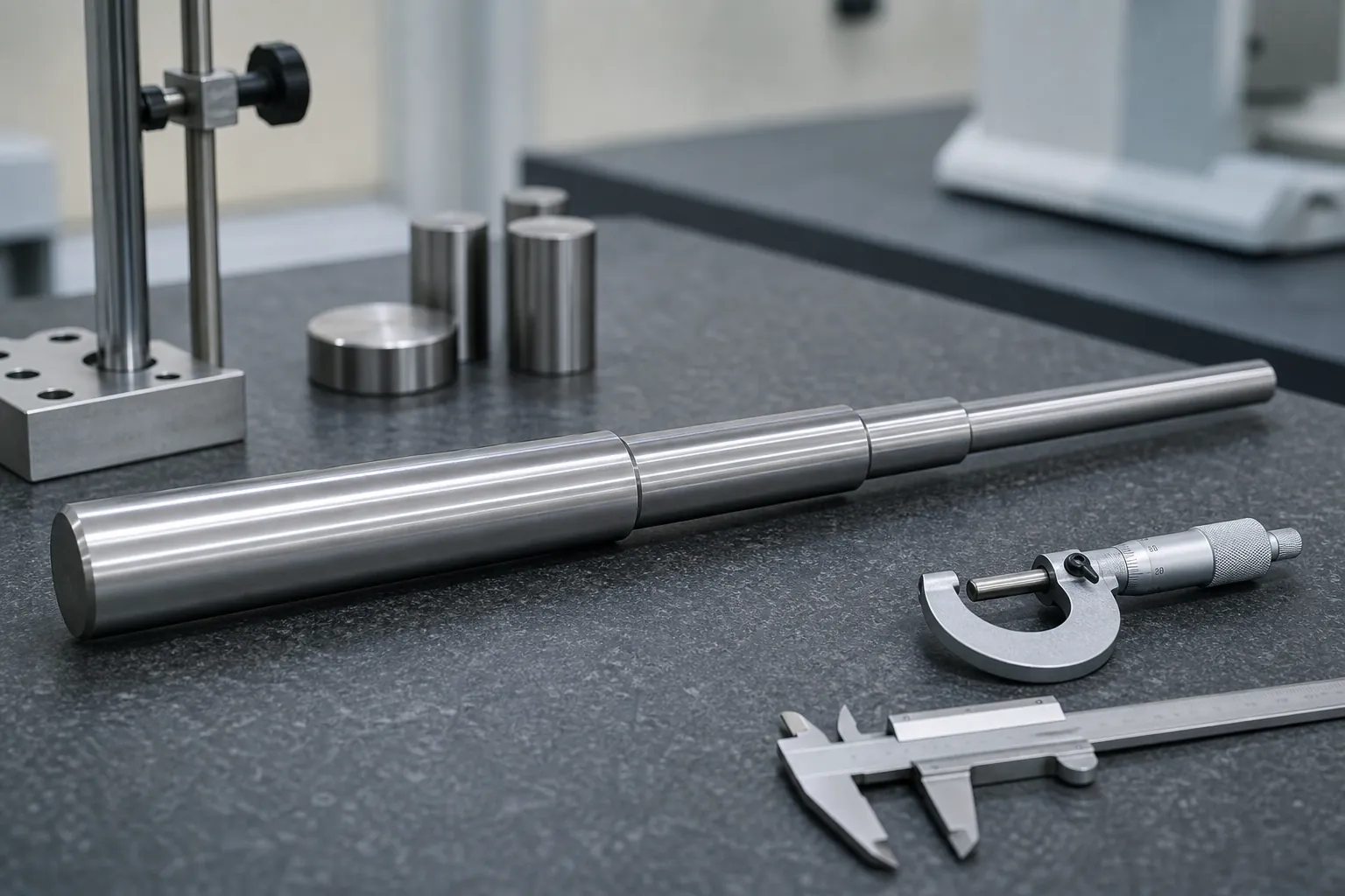
O desafio apresentado pelos Medical Bits
O projeto envolveu a produção de bits médicos especializados. Estes componentes tinham um conjunto único de especificações que representavam um desafio considerável para as nossas máquinas e equipas técnicas. As dimensões da peça foram precisamente 7.9*230, e apresentava um diâmetro de haste que se estreitava de 7.9 – 6.9 – 5.9, com 3 etapas distintas ao longo de seu comprimento. Esses requisitos complexos e precisos exigiam o mais alto nível de exatidão e precisão em nossos processos de fabricação.
A fabricação de componentes médicos não é tarefa fácil. Qualquer desvio das especificações exigidas pode ter consequências graves, especialmente na área médica, onde a segurança e a confiabilidade são de extrema importância. Nossa equipe estava bem – ciente da gravidade da tarefa em questão. Sabíamos que tínhamos que fazer todos os esforços para garantir que o produto final atendesse aos rígidos padrões de qualidade do cliente..
Engineering Review: Why a Stepped Medical Drill Is Hard to Straighten
Reading this project as engineers rather than storytellers, the workpiece specification explains the difficulty on its face. UM 230 mm length stepping down through three diameters is not one slender rod but three slender rods joined in series, each with different stiffness. Correction force applied at one diameter produces different deflection per unit force at each step, the bend peak tends to sit near the stiffness transitions rather than at mid-length, and any measurement that treats the part as a uniform shaft misreads the geometry it is supposed to control. On top of the section problem, medical tooling acceptance is unforgiving: at a 0.05 requisito de retilineidade mm, the measurement method itself becomes a first-order participant, and the part’s function — a cutting instrument rotating predictably — leaves little room for the marks or residual distortion that a careless correction route would trade away for geometry.
Datum Selection Decides the Project Before the First Press
On a stepped shaft, which features define the measurement reference is not a detail — it is the project. Centering on the end center holes references the axis the part will rotate about in service; referencing the largest finished diameter makes the biggest section the anchor and reads the smaller steps against it; referencing a functional flank or flute zone answers what the tool actually needs straight, but demands feature-aware measurement. Each choice gives different numbers on the same part, so it must be agreed with the customer before trials, not discovered at acceptance. The framework for exactly this decision — including the reseating checks that prove the datum is being realized repeatably — is laid out for seleção de referência de medição de eixo escalonado. For the sample test that then validates the correction route against that datum, the evidence rules in endireitando teste de amostra e aceitação apply unchanged to medical tooling.
Step transitions deserve their own respect in the correction plan. The change of section concentrates stress at the shoulder, so correction strokes are planned to avoid loading a shoulder in bending where an alternative press location exists, and the flank surfaces of a cutting tool are treated as protected zones in the same discipline described for broca de canhão e endireitamento de broca de furo profundo — the closest industrial cousin of this workpiece family.
How the Trial Was Executed
The trial work concentrated on two things: the correction plan for a 0.05 mm tolerance, and inspection between stages. Posições de apoio, press points and stroke settings were fixed and recorded before the first correction, because the tolerance left no room for improvised strokes. Intermediate inspections after each stage caught deviations while they were still correctable, instead of inspecting defects in afterwards.
The Result: 0.05 mm as Required
A retilineidade da peça de trabalho após endireitamento reached 0.05 milímetros, on the mark of the client’s requirement. How that number was measured is documented in the verification section below.
The client expressed satisfaction with the results and interest in future collaboration. The transferable engineering lessons are summarized in the final section of this article.
Olhando para o futuro
This case is one sample lot on one workpiece family; the sections above record what was measured and what carried the result. The next project starts from the drawing and its tolerance callout, not from this narrative.
How a Result Like This Is Verified Rather Than Declared
A straightness result at the 0.05 mm level is a joint property of the part and the measurement system, so the verification chain is what makes the number meaningful. The chain that supports a claim of this class runs: an agreed datum and support condition, written into the inspection instruction; a gauge whose repeatability on this part family has been demonstrated — because at tight tolerances the gauge’s own scatter is a visible fraction of the limit, the discipline of medidor R&R para endireitar linhas is not optional; released-state measurement after correction force is fully removed, por loaded versus released practice; and correlation to the customer’s own reference method on matched parts, so both sides of the shipment read the same part the same way. Within that chain, a supplier’s internal reading and the customer’s acceptance gauge agreeing is the result — the individual number on either instrument alone is only an interim.
What Transfers From This Case to Other Workpieces
The specific workpiece belongs to one client, but the engineering pattern repeats across families. Primeiro: on stepped or tapered slender parts, build the correction plan around the stiffness map, not the single worst reading. Segundo: fix the datum definition with the customer before any trial stroke, and prove its repeatability with reseating checks. Terceiro: treat functional surfaces — flutes, arestas de corte, finishing zones — as protected zones with explicit contact rules, in the discipline shared with stepped medical drill straightening e small-diameter medical drill applications. Fourth: let the acceptance evidence — released-state measurement on the agreed gauge, with rework limits and disposition defined in advance — be the arbiter, not the optimism of the production floor. Parts that follow those four rules converge in fewer strokes and survive audit; parts that skip them consume rework budgets learning the same lessons again.
Perguntas frequentes
Why do stepped shafts bend near the diameter transitions?
Because stiffness changes abruptly at each shoulder. Stress from handling, heat treatment and prior machining concentrates where the section changes, and the transition acts as a hinge under any later load. Correction plans for stepped parts therefore map the shoulders explicitly and place press points with the stiffness map in view, rather than assuming a uniform rod.
É 0.05 mm straightness limited by the machine or the measurement?
At that level, both matter and the measurement usually dominates the conversation. The gauge’s own repeatability is a visible fraction of the tolerance, so the datum, support condition and gauge capability must be demonstrated before any correction result can be interpreted. This is why tight-tolerance projects front-load the measurement work.
Can flute zones be used as contact points during correction?
Generally not. Flutes and cutting edges are functional surfaces, and contact there risks edge damage that no straightness gain justifies. Correct practice places supports and press contact on the plain shank or agreed non-functional zones, with tooling geometry that spreads the load — the contact-zone discipline shared across tool straightening applications.
If this is your first drill bit straightening line, leia o passo a passo de seleção de alisador primeiro, em seguida, compare seu orçamento com o acceptance test checklist for a new machine.