
A welded fabrication is not a uniform shaft, bar or beam. It may combine box sections, plates, buizen, crossmembers, gussets, bazen, mounting pads, holes and brackets in one three-dimensional assembly. Welding shrinkage, sequence, restraint, snijden, handling and stress relief can move several functional features at the same time.
A reliable welded structure straightening press must therefore control a complete load path, not simply push the highest visible point. The solution must answer five questions before machine selection:
- Which functional datums and interfaces define an acceptable assembly?
- Is the error global bow, twist, angular distortion, local panel buckling, hole/boss displacement or fixture-induced error?
- Where may supports, reaction blocks and hydraulic heads contact without damaging thin panels, tenen lassen, machined pads or holes?
- Kan het werkstuk stil blijven staan terwijl de portaal- of correctiekoppen naar elk punt bewegen??
- Hoe wordt het onbelaste samenstel opnieuw gemeten?, lasgeïnspecteerd en vrijgegeven na elke correctiereeks?
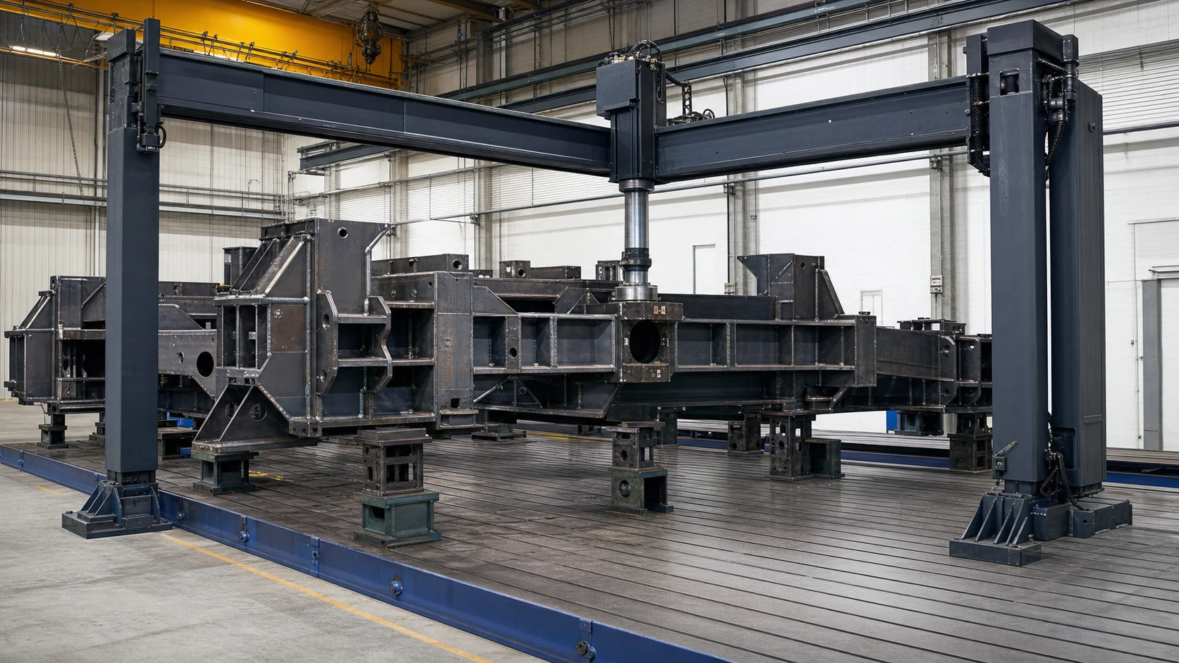
*Technische conceptillustratie van een groot laswerk op een richtpers met een breed bed en een reisportaal. Het is geen foto op de locatie van de klant of een prestatieclaim. Werkelijke bedgrootte, ondersteunt, correctie hoofden, kracht- en acceptatielimieten vereisen gecontroleerde fabricage en representatieve monstertests.*
Definieer de fabricagefamilie voordat u de pers ontwerpt
| Werkstukfamilie | Typische kenmerken | Belangrijkste uitdaging voor het rechttrekken |
|---|---|---|
| Machineframe of basis | Vaksecties, machinaal bewerkte montagepads, rails en bazen | Globale twist plus coplanariteit van functionele interfaces |
| Gelast chassis of subframe | Lange rails, crossmembers, beugels en ophangingsinterfaces | Diagonale relatie, lokale knooppuntbeweging en vervorming over meerdere assen |
| Lassen van zware apparatuur | Dikke platen, gegoten/gesmede inzetstukken, hoekplaten en draaiboringen | Hoge reactiebelastingen en uitlijning van boring tot remblok |
| Kast- of behuizingsframe | Dunne panelen met lokale versteviging en deur/afdichtingsinterfaces | Lokaal knikken en ontoegankelijke reactiepunten |
| Gelaste steun- of beugelmontage | Meerdere platen, gaten en bevestigingsvlakken | Hoekvervorming en positie van gatenpatroon |
| Grote structurele fabricage | Lange open profielen en verbindingsplaten | Behandeling, verzakking en globale 3D-geometrie |
| Oxy-fuel of plasma-gesneden gefabriceerde vorm | Snijplaatvervorming plus latere laskrimp | Scheid de vlakheid van de plaat van de uitlijning van het samenstel |
| Nabewerkt laswerk | Afgewerkte kussentjes, boringen en oppervlakken | Functionele oppervlaktebescherming en beperkt correctievenster |
Deze pagina behandelt de gecontroleerde correctie op de werkvloer van driedimensionale lasconstructies. Gebruik de speciale liggeroplossing voor flensvervorming van I/H-liggers, het plaatproces voor het egaliseren van vlak materiaal, en het asproces voor roterende componenten. Reparatie van botsingsframes in de auto-industrie en veldcorrectie van belaste constructies vallen buiten deze productieworkflow.
Bevries de productiefase
Na hechtlassen
Het samenstel kan nog steeds in de bouwbevestiging worden vastgehouden en vertegenwoordigt mogelijk niet de vrijgegeven geometrie ervan. Meting in een ingesloten armatuur kan niet worden beschouwd als definitieve acceptatie in de vrije staat. Vroegtijdige correctie kan de lasvolgorde ten goede komen, maar latere laspassages kunnen vervorming veroorzaken.
Na volledig lassen
De lasvolgorde en de fixatie zijn voltooid, maar de structuur kan nog steeds koeling vereisen, reiniging en inspectie. De geschiktheid voor correcties is afhankelijk van de lasstatus, materiaal, dikteovergangen en de goedgekeurde productieprocedure.
Na stressverlichting of warmtebehandeling
Thermische verwerking kan de geometrie en materiaalreactie veranderen. Een recept dat vóór stressverlichting is ontwikkeld, mag niet zonder revalidatie worden overgedragen.
Vóór het bewerken
Wanneer er nog voorraad is op functionele pads of boringen, rechttrekken kan de bewerkingstoeslag herstellen en de stroomafwaartse instelfouten verminderen. Het proces moet dezelfde functionele nulpuntstrategie gebruiken als gepland voor de bewerking.
Na bewerking of coating
Afgewerkte boringen, kussentjes, geleidingsoppervlakken, verf en verzinken worden beschermde eigenschappen. Het correctievenster is smaller, en post-process dimensionale en oppervlakte-inspectie wordt verplicht.
Bouw een functionele 3D-datumketen
Het richtdoel moet afkomstig zijn van de teken- en montagefunctie, niet vanaf welk oppervlak dan ook het gemakkelijkst te bereiken is met een liniaal.
Het meetplan moet definiëren:
- primair, secundaire en tertiaire datums;
- vlakheid en coplanariteit van het montagepad;
- boring- of naafassen en hartafstanden;
- gatenpatroonpositie en diagonale relatie;
- frame boog, twist en dwarsbalk haaksheid;
- interface hoogte, parallellisme en hoekrelatie;
- datum-ondersteuningsposities, contactkracht en terughoudendheidstoestand;
- uitsluitingszones rond laswapening, spatten en ruwe vlamgesneden randen;
- temperatuur, koel- en stabilisatieconditie;
- herhaalbaarheid na het lossen, roteren en opnieuw klemmen;
- correlation with the customer's CMM, lasertracker, armatuur of functionele meter.
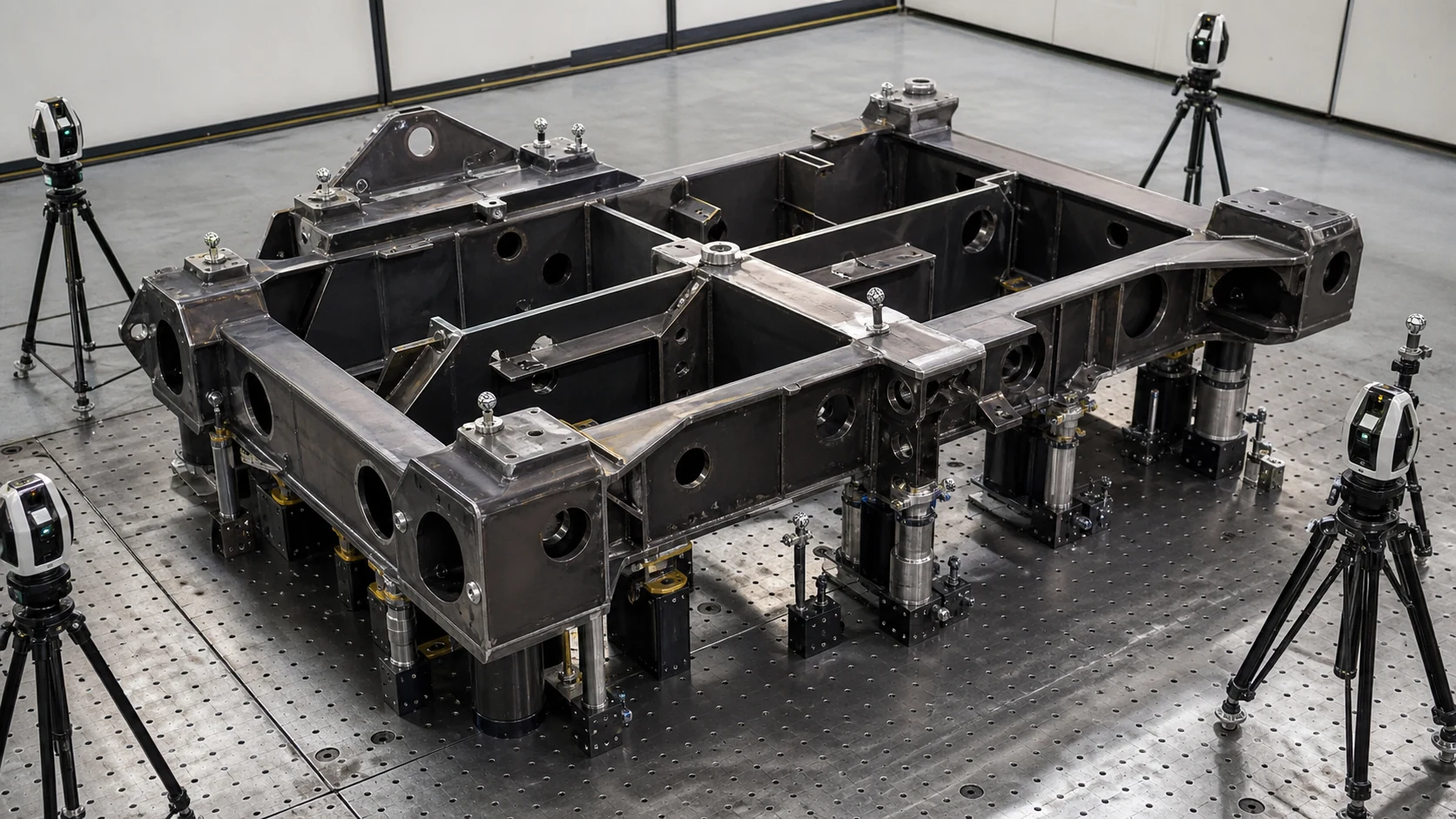
*Engineering concept illustratie van een laswerk gemeten vanaf gecontroleerde datumsteunen en functionele doelen. Het is geen voorgeschreven sensorindeling. Werkelijke doellocaties, coördinatensysteem en acceptatieberekeningen vereisen de correlatie van de tekening en de klantmeter.*
Aparte vervorming door beschadiging en armatuurfout
| Waargenomen signaal | Mogelijke oorzaak | Vereiste route |
|---|---|---|
| Gladde frameboog herhaald na loslaten en herladen | Globale laskrimp of vormingsvervorming | Kandidaat voor gecontroleerde lange-spancorrectie |
| Tegenoverliggende hoeken bewegen in verschillende Z-richtingen | Globale twist of diagonale vervorming | Meerpunts 3D-meting en torsiebewuste correctie |
| Eén beugel of nok is verplaatst terwijl het hoofdframe stabiel is | Lokale warmte-inbreng, volgorde of hechtingsbeperking | Lokale knooppuntcorrectie met geverifieerd reactiepad |
| Dun paneel toont golven tussen verstijvingen | Lokaal knikken of olieconserven | Paneelspecifieke engineeringroute; pas geen generieke puntbelasting toe |
| De geometrie verandert wanneer klemmen of steunen bewegen | Armatuur terughoudendheid, onstabiele ondersteuning of doorbuiging van zware onderdelen | Bevries de nulpuntconditie en herhaal de meting |
| Afleesveranderingen nadat spatten of coating zijn verwijderd | Oppervlakteverontreiniging of vals doelwit | Reinig en kwalificeer het meetoppervlak |
| Vervorming valt samen met scheur, ondergraven, indicatie van gebrek aan versmelting of gescheurd materiaal | Las- of basismetaaldefect | Inspectie en reparatie vóór het rechttrekken |
| Montageblokken zijn coplanair, maar het boorpatroon is verkeerd | Fabricage, bewerkings- of kenmerklocatiefout | Functiespecifieke instelling; mondiale druk kan het nog erger maken |
Rechttrekken verandert de geometrie. Het repareert een onaanvaardbare las niet, scheur, lamineren, gescheurd gat, ontbrekend gedeelte of niet-goedgekeurde thermische schade.
Inspecteer de lassen voordat u correctiekracht uitoefent
De binnenkomende poort zou dit moeten bevestigen:
- traceerbaarheid van materialen en lasprocedures;
- lassen, verkoeling en stressverlichting;
- visuele inspectie;
- vereiste niet-destructieve inspectiestatus voor kritische lassen;
- bekende reparatielocaties en eerdere correctiegeschiedenis;
- scheur, ondergraven, porositeit, gebrek aan fusie of een andere relevante indicatie;
- afgewerkte oppervlakken, coatings en kenmerken die beschermd moeten blijven;
- technische goedkeuring voor de geplande mechanische correctiefase.
De exacte inspectiemethode en acceptatiewaarden behoren tot de toepasselijke tekening, lascode en klantkwaliteitsplan. Een groen geometrieresultaat kan een onaanvaardbare las- of basismetaalconditie niet opheffen.
Ontwerp de steun- en reactiekaart
Elke perskracht heeft een volledig traject door het werkstuk en in het machinebed nodig. De kaart moet identificeren:
Standaard beschermde of beoordelingszones
- niet-ondersteunde dunne platen of panelen;
- tenen lassen, start/stopt en niet-geïnspecteerde lasindicaties;
- machinaal bewerkte montagepads, geleidingsvlakken en afdichtingsvlakken;
- verveelt, gaten, draden en lokalisatiefuncties;
- scherpe sectieovergangen en vrije plaatranden;
- identificatie- en traceerbaarheidstekens;
- coatings en architectonisch blootgestelde oppervlakken;
- gebarsten, stuk, ernstig gecorrodeerde of eerder gerepareerde zones.
Potentieel goedgekeurde laadzones
- versterkte knooppunten waar dwarsbalken, hoekplaten en gesloten profielen brengen kracht over;
- brede structurele gronden ondersteund tegen lokaal knikken;
- vervangbare contactvlakken afgestemd op het werkelijke oppervlak en toegestane markering;
- tijdelijke toolinginterfaces opgenomen in het gecontroleerde procesontwerp;
- reactiepunten geverifieerd door tekeningbeoordeling, monstertesten en, wanneer nodig, technische analyse.
Reactieblokken moeten in drie dimensies verstelbaar zijn zonder dat dit ongecontroleerde harde punten worden. Een steun die voor één framerevisie werkt, kan onder een gat vallen, las teen of dun paneel op een andere.
Selecteer de persarchitectuur uit Geometrie en Handling
Reisportaalpers met breed bed
Savage Engineering beschrijft publiekelijk breedbed-laspersen met drie-assige rambeweging, zodat grote werkstukken stationair kunnen blijven terwijl de ram naar de gewenste locatie beweegt. Hidrogarne beschrijft op soortgelijke wijze een beweegbaar portaal en een zijdelings bewegende kop voor toegang tot verschillende correctiepunten zonder de constructie herhaaldelijk te verplaatsen.
Deze architectuur is geschikt voor grote ruimtes, zware of onhandige lasnaden:
- het hele onderdeel en zijn steunen passen op een stijf referentiebed;
- het portaal en de kop kunnen alle goedgekeurde correctieknooppunten bereiken;
- hydraulische werkliften of ondersteuningssystemen positioneren reactieblokken veilig;
- de besturing beperkt de rampositie, kracht, verplaatsing en iteratie;
- vrijgegeven geometrie wordt gemeten na het verwijderen van actieve correctiebelasting.
C-frame of multi-actiepers
Beckwood beschrijft C-framesystemen met meerdere onafhankelijk gecontroleerde acties voor grote lasverbindingen en gefabriceerde samenstellingen. Deze aanpak is geschikt voor gelokaliseerde vervorming waarbij verschillende reactie- en correctierichtingen moeten worden gecoördineerd en open toegang vereist is.
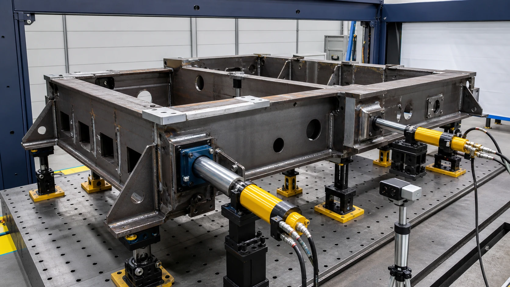
*Engineering concept illustratie van onafhankelijk gepositioneerde correctiekoppen en reactiesteunen die werken via versterkte knooppunten. Het is geen universeel armatuur. Paden laden, lokale spanning, las conditie, De stijfheid en terugvering van de ondersteuning vereisen technische beoordeling en monstervalidatie.*
Horizontale bulldozerpers
Een zijdelings werkende horizontale pers kan het laden van lange frames vereenvoudigen, chassisleden en structurele componenten. Het vereist nog steeds een stabiele zijdelingse bevestiging en een geverifieerd excentrisch laadpad.
Warmte rechttrekken
Warmte rechttrekken is een aparte gecontroleerde procedure met materiaal, lassen, temperatuur- en kwalificatievereisten. Op deze pagina wordt ongecontroleerde toortsverwarming niet behandeld als een uitwisselbaar alternatief voor gemeten mechanische correctie.
Lezen druk rechttrekken versus rollen rechttrekken voor de algemene methodevergelijking. Complexe laswerken vereisen normaal gesproken punt- of meervoudige correctie in plaats van een generiek recept voor doorvoerrollen.
Gebruik een gesloten lus voor vrijgegeven onderdelen
- Identificeer de fabricagefamilie, tekeningrevisie en productiefase.
- Bevestig of u in aanmerking komt voor lasinspectie en correctie.
- Reinig het werkstuk en bescherm functionele interfaces.
- Laad het op het gecontroleerde referentie- en steunarrangement.
- Meet de volledige 3D-geometrie en classificeer elke foutcomponent.
- Selecteer goedgekeurde ondersteuning, reactie- en correctiepunten.
- Positioneer de portaal- of correctiekoppen zonder het referentiepunt onnodig te verplaatsen.
- Oefen een begrensde kracht of verplaatsing uit via het geverifieerde belastingspad.
- Ontlast de correctiekracht volledig en stabiliseer het werkstuk.
- Meet dezelfde objecten opnieuw in hetzelfde coördinatensysteem.
- Herhaal dit alleen met kracht, verplaatsing, lokale vervormings- en iteratielimieten.
- Voltooi de vereiste las, oppervlakte- en functionele interfacecontroles.
- Binnenkomend opslaan, tussen- en eindgeometrie met de merkidentiteit.
De regeling moet voorkomen dat een OK-maat een onderdeel met een NOK-las automatisch loslaat, beschadigd oppervlak of overschreden proceslimiet.
Hantering en veiligheid van zware onderdelen
Grote lasnaden brengen risico's met zich mee die verder gaan dan het perstonnage. De cel heeft het misschien nodig:
- kraan- of transferkarbelading met gedefinieerde hefpunten;
- hydraulische werkliften voor het positioneren van steunen en reactieblokken;
- architectuur met vaste onderdelen om herhaalde kraanbewegingen te verminderen;
- zwaartepunt- en stabiliteitscontroles voor elk gezin;
- vergrendelingen rond de portaalverplaatsing, hoofdbewegingen en hangende lasten;
- veilige toegang voor inspectie en gereedschapswisseling;
- beschermde slangen, kabels en sensoren buiten het lastpad;
- Receptbevestiging van onderdeeloriëntatie en tekeningrevisie;
- gecontroleerd herstel na een gestopte of onvolledige correctiecyclus.
De machinecapaciteit moet worden geselecteerd op basis van het slechtst gevalideerde belastinggeval, inclusief excentrisch laden en beddekking, niet van één enkel nominaal tonnagenummer.
Vereiste informatie voor een technisch voorstel
| Invoer | Minimale details |
|---|---|
| Definitie van het werkstuk | Montagetekening, herziening, algehele envelop, massa en zwaartepunt |
| Materialen | Cijfers, diktes, warmtebehandeling en verbindingen van verschillend materiaal |
| Lasproces | Reeks, procedure, inspectie staat, reparatiegeschiedenis en stressverlichting |
| Functionele datums | Montage-pads, verveelt, bazen, gaten en interfacehiërarchie |
| Foutkaart | Inkomende 3D-metingen, boog, twist, hoekige en lokale vervorming |
| Beschermde functies | Dunne panelen, lassen, bewerkte oppervlakken, gaten, draden en coatings |
| Vereist resultaat | Tolerantie tekenen, coördinatensysteem, datumbeperking en meetmethode |
| Toegang laden | Goedgekeurde correctie- en reactiezones plus verboden contactgebieden |
| Behandeling | Laadmethode, punten optillen, oriëntatie, rotation and facility constraints |
| Productiebehoefte | Productmix, doel verslaan, omschakeling, automatisering en traceerbaarheid |
| Geldigmaking | Sample quantity, worst-case families, correlatie meten, FAT/SAT en rapportformaat |
Als deze invoer onvolledig is, the correct first deliverable is a measurement, support and sample-test plan—not an invented tonnage, nauwkeurigheid of cyclustijd.
Van monstertest tot productierelease
- Beoordeel tekeningen, weld documents and quality requirements.
- Build a family matrix for geometry, massa, datums and protected features.
- Freeze the 3D measurement coordinate system and support condition.
- Inspect representative normal and worst-case samples.
- Model or review the proposed load and reaction paths.
- Trial bounded correction on approved samples.
- Quantify springback, cross-axis movement, local deformation and repeatability.
- Reinspect welds, surfaces and functional interfaces.
- Correlate released results with the customer's CMM, tracker or functional fixture.
- Gereedschap bevriezen, recepten, limits, safety logic and traceability fields.
- Loop monstertest en acceptatie voordat de gevalideerde familie wordt vrijgelaten.
Send us your weldment drawing, 3D inspection report, lasstatus en kaart met beschermde kenmerken een richt- en hanteringsconcept te ontvangen. StraighteningTech ontwikkelt de persarchitectuur, ondersteunend gereedschap, meet- en verificatieworkflow rond de daadwerkelijke fabricage in plaats van een algemene persopstelling toe te passen.