
Gearbox input, output and intermediate shafts combine smooth bearing journals with gears, spieën, schouders, groeven, center holes and sometimes radial oil holes. Hittebehandeling, rough machining, gear cutting and handling can introduce global bow or local runout that affects later grinding, gear inspection and assembly.
A gearbox shaft straightening solution therefore cannot treat the part as a plain round bar. The process must establish functional datums, separate journal runout from gear-related measurement, exclude fragile features from the force path, apply limited over-bending and remeasure all controlled stations. Final force, steun spanwijdte, hartinfarct, accuracy and cycle time must be confirmed from drawings and representative sample tests.
Why Gearbox Shafts Need a Dedicated Straightening Process
Primary and secondary transmission shafts commonly require more than one correction position. Galdabini describes two or three straightening points and gear pitch-diameter checking with a master gear for this workpiece family. KBH describes automatic transmission-part lines with center cleaning, complete measurement at multiple stations, crack-formation control and final remeasurement. These are useful process references, but they are not performance evidence for a StraighteningTech machine or for a specific customer part.
| Workpiece feature | Straightening consequence |
|---|---|
| Multiple bearing journals | Measurement must preserve the drawing datum relationship between journals |
| Helical or spur gear section | Tooth-tip readings cannot automatically be treated as shaft-center runout |
| Spline | Requires functional measurement or a validated reference surface; teeth must be protected |
| Radial oil hole or cross-hole | Pressing across the hole can create a local stress concentration |
| Schouders, grooves and fillets | Poor default support or pressing zones because stiffness changes locally |
| Heat-treated surface | Springback and crack risk must be evaluated by batch and process condition |
| Dirty or damaged center holes | Center-based measurement can become unreliable unless the centers are inspected and cleaned |
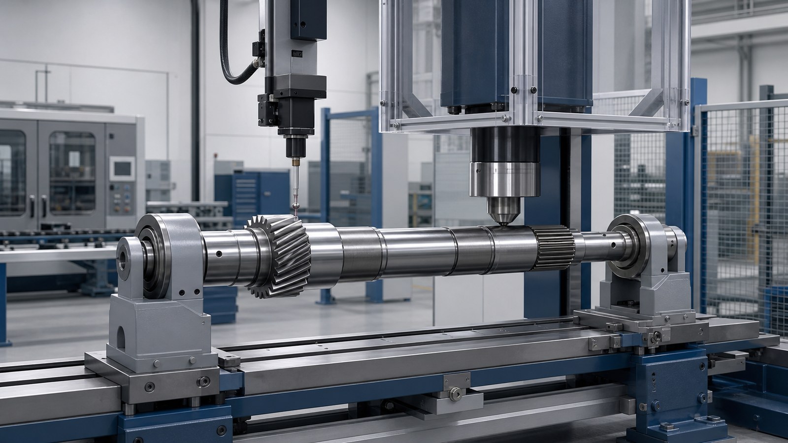
*Concept illustration: the image explains a possible measurement and correction arrangement. It is not a customer-site photograph or proof of a supplied machine configuration.*
Define the Acceptance Characteristic First
Rechtheid, radial runout and gear pitch-diameter variation are related to different functional characteristics. A low indicator reading on one journal does not prove that the gear, spline and remaining journals share the required axis. The drawing and inspection plan must define what is controlled and which surfaces establish the datum.
| Control item | Possible method | Datum / contact rule | Project status |
|---|---|---|---|
| Journal radial runout | Contact displacement probe or validated non-contact sensor | Rotate from drawing-defined centers or journals | Confirm from drawing |
| Axis straightness | Multi-station displacement measurement | Defined support condition and axial stations | Confirm from drawing |
| Gear pitch-diameter runout | Master gear, ball probe or validated laser method | Functional gear datum and controlled mesh | Confirm gear specification |
| Spline functional runout | Spline master or validated functional gauge | Do not infer from tooth-tip contact alone | Confirm spline standard |
| Surface condition | Visual and agreed surface inspection | All support, probe and press contact areas | Confirm acceptance sample |
| Crack control | Approved NDT method where required | High-stress zones and post-correction condition | Confirm risk and quality plan |
ISO 1101 provides the general geometrical-tolerancing language, but it does not choose the correct datum or gauge for an individual gearbox shaft. The machine recipe must match the controlled drawing revision and the customer’s final inspection method.
Measurement Strategy for Journals, Gears and Splines
1. Establish a repeatable rotational datum
Use center holes, finished journals or another drawing-defined datum only after confirming that the surfaces are clean, undamaged and appropriate for the manufacturing stage. Center holes affected by heat-treatment residue can shift the apparent bend direction, so inspection or automatic cleaning may be necessary before measurement.
2. Measure several axial stations
One probe cannot describe a stepped shaft. Measure the relevant journals and lands at fixed axial positions while the shaft rotates. The control system should reject readings from grooves, reliefs, holes, keyways and interrupted surfaces rather than treating every peak as bending.
3. Evaluate the gear as a functional feature
A master gear can evaluate the pitch-diameter relationship, while tactile or laser alternatives may suit other gear types. MAE notes that master-gear runout and surface-form effects must be separated from workpiece runout. The selected method must be correlated with the customer’s gear inspection equipment.

*Concept illustration: smooth journals are measured separately from the gear section, and the radial-hole position is identified before a correction zone is selected.*
Build a Protected Correction Map
The maximum measured deviation is not automatically the correct press location. The algorithm must choose from approved correction lands and keep high-risk features outside the support and press path.
| Zone | Default rule | Reason |
|---|---|---|
| Stable smooth cylindrical land | Candidate measurement, support or press zone after stress review | Predictable contact and section stiffness |
| Gear teeth and spline | No direct press contact | Risk of profile damage and false functional geometry |
| Radial or cross-hole | Exclude from the primary force path | Local section loss and stress concentration |
| Shoulder, groove and fillet | Avoid unless specifically engineered | Abrupt stiffness change and marking risk |
| Finished bearing or seal journal | Contact only with validated protected tooling | Surface damage can affect assembly or sealing |
| Hollow or deeply bored section | Verify section capacity before pressing | Local ovalization or collapse may occur |
Radial-hole orientation can be detected before correction so the shaft is not loaded through its weakest angular position. Force and displacement limits should also stop the cycle when the expected response is not obtained.
Aanbevolen gesloten-lus-richtproces
For most stepped gearbox shafts with local bend, automatic press straightening is preferred over a generic through-feed roller process. Point correction provides access to selected lands and allows separate recipes for different shaft variants. Roller straightening may remain suitable for simpler blanks before gear and spline features are finished, but it should not be assumed suitable for every completed gearbox shaft.
- Identify the part and load the controlled recipe.
- Inspect or clean the center holes and approved datum surfaces.
- Locate the shaft axially and establish repeatable rotation.
- Measure all drawing-defined journal and functional gear stations.
- Filter interrupted-surface effects and calculate bend magnitude and angular direction.
- Detect radial-hole orientation and exclude prohibited correction zones.
- Position supports and press tooling on approved lands.
- Apply a limited correction under force and displacement monitoring.
- Release the load and remeasure every affected station.
- Alleen herhalen binnen gevalideerde slag, force and iteration limits.
- Complete final functional measurement, surface inspection and any required crack check.
- Record OK, NOK or engineering-review status with the recipe and measurement results.
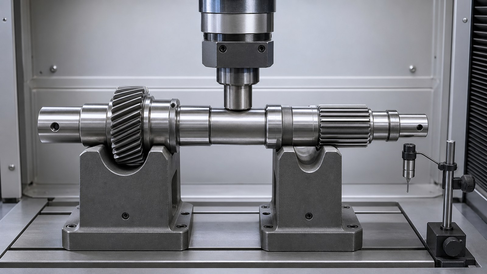
*Concept illustration: the press and supports act on smooth approved lands while teeth, spieën, shoulders and cross-holes remain outside damaging contact.*
Springback and Crack-Risk Control
Heat-treatment condition, material strength, local section changes and incoming bend history all affect springback. A fixed stroke copied across batches can under-correct one shaft and over-correct another. The controller should update the next stroke from the released, remeasured result rather than from the loaded deflection alone.
The process also needs hard safety limits. Maximale kracht, displacement, iteration count and residual error should be set during sample development. If correction response becomes non-linear, if the shaft exceeds an incoming-reject envelope, or if a protected feature enters the force path, the machine should stop and route the part for engineering review.
Crack control is application-specific. It may include force-curve monitoring, surface inspection or a customer-approved NDT method. A straightening machine must not claim “zero cracks” merely because a force limit exists.
Aanbevolen celconfiguratie
| Module | Recommended concept | Engineering purpose |
|---|---|---|
| Machine principle | Servo-electric or servo-hydraulic point press | Controlled local correction with recipe limits |
| Datum and rotation | Centra, journal rollers or dedicated clamping | Repeatable angular measurement without damaging features |
| Journal measurement | Multiple contact probes or validated laser sensors | Map bend and runout at drawing-defined stations |
| Gear / spline measurement | Master gear, functional master, ball probe or validated laser | Measure the torque-transmitting feature correctly |
| Feature detection | Radial-hole and orientation sensor when required | Prevent pressing through fragile sections |
| Gereedschap | Adjustable contoured supports and protected press tips | Keep stress and contact marks within validated limits |
| Controle | Recipe, filtering, adaptive stroke and iteration limits | Manage springback and part variants |
| Kwaliteit | Final remeasurement, OK/NOK sorting and data record | Prevent unverified parts from flowing downstream |
| Automatisering | Handmatig laden, conveyor, gantry or robot | Match volume, layout and changeover needs |
The matching machine must be sized from the shaft drawing, materiële toestand, maximum incoming bend and sample-test force. Bekijk de UBS20MF4000 Poortrichtmachine only as a machine-family reference; its suitability and any performance value require project-specific confirmation.
Sample Validation Plan
This page is a concept-level solution, not a manufacturing case. Before a quotation or accuracy statement, test representative samples covering minimum and maximum shaft length, journal diameter, gear geometry, material strength, heat-treatment batch and incoming bend.
Record the controlled drawing revision, datum setup, incoming readings, correctie positie, force and displacement, iteration count, released final readings, surface condition and crack-inspection result. Machine and customer gauges must be correlated on the same parts. A reported accuracy or cycle time becomes publishable only when the characteristic, sample count, gauge and acceptance record can be verified.
Information Needed for a Gearbox Shaft Proposal
Please send:
- controlled part drawing and revision;
- shaft function: input, output, intermediate or pinion shaft;
- materiaal, hardness and heat-treatment condition;
- manufacturing stage at straightening;
- total length, journal diameters, gear and spline data;
- center-hole, radial-hole, groove and shoulder locations;
- incoming bend or runout distribution;
- drawing-defined datum and target characteristic;
- customer gauge or correlation samples;
- prohibited contact zones and surface criteria;
- productievolume, cycle target and changeover matrix;
- loading, traceability and plant-layout requirements.
These inputs allow our straightening solution team to select the measurement method, force path, gereedschap, correction limits and sample-validation plan without inventing unsupported parameters.
Veelgestelde vragen
Can a gearbox shaft be measured only on its bearing journals?
Only when the drawing and downstream function permit it. Gear or spline runout may require a functional master or another validated method in addition to journal measurement.
Can the machine press directly on a gear or spline?
Direct contact is normally avoided because it can damage the profile and create an unreliable force path. Approved smooth lands and dedicated tooling should be defined from the drawing.
How are radial oil holes protected?
The hole location can be detected or mechanically indexed, and the recipe can prohibit press directions that load through the weakened section. The final rule must be validated on representative parts.
What straightening accuracy can be guaranteed?
No universal value can be guaranteed from the workpiece name alone. The achievable result depends on geometry, materiaal, warmtebehandeling, binnenkomende vervorming, gegeven, gauge correlation and the agreed sample test.
Does every shaft need crack detection?
Nee. Crack inspection should follow the material, heat-treatment condition, correction strain and customer quality plan. High-risk applications may require an integrated or downstream approved NDT method.
Discuss Your Gearbox Shaft Project
Explore our Automotive Straightening Solutions, review the matched gate point straightening machine family, of contact our straightening solution team with your drawing and sample matrix.