
Stud bola panjang bukanlah palang bulat biasa dan ia bukan pemasangan batang seri yang lengkap. Ia menggabungkan batang langsing dengan kepala bola yang sangat sarat, jejari peralihan dan, bergantung pada peringkat pembuatan, rumah pangsa, sebuah tirus, benang atau permukaan galas siap. Kaedah meluruskan mesti membetulkan batang yang boleh digunakan tanpa menggulung atau menekan pada zon berfungsi yang tidak direka bentuk untuk sentuhan.
Atas sebab ini, penyelesaian meluruskan stud bola panjang bermula dengan laluan lukisan dan pembuatan. Proses penggelek mungkin cekap untuk batang yang cukup seragam dan kelengkungan teragih; pembetulan titik yang diukur mungkin lebih selamat apabila panjang sentuhan roller yang boleh digunakan adalah pendek atau apabila bahagian telah selesai ciri yang memerlukan sentuhan terpilih.
Kancing Bola, Ball Joint dan Tie Rod Adalah Produk Yang Berbeza
ZF menerangkan sambungan bola casis sebagai stud bola keluli yang berjalan dalam cawan galas yang dilincirkan di dalam perumah. ZF juga menerangkan rod pengikat sebagai penghubung yang mengandungi sambungan bola dalam dan luar yang disambungkan oleh benang pelaras. Bahan kerja dalam foto projek adalah kosong stud bola panjang individu, tidak dipasang sambungan bola atau batang pengikat.

Imej itu mengesahkan kosong jenis stud bola panjang permukaan hitam sebenar dengan kepala bola dan badan langsing. Ia tidak mewujudkan gred keluli, kekerasan, dimensi, geometri akhir atau penerimaan pelanggan.
| Produk/ciri | Meluruskan implikasi |
|---|---|
| Kancing bola tempa sejuk kosong | Skala dan variasi dimensi mempengaruhi pemakanan, sentuhan dan pengukuran |
| Kepala bola | Mesti dipandu atau dibersihkan tanpa merosakkan permukaan galas masa hadapan |
| Peralihan kepala ke batang | Kepentingan geometri dan keletihan yang tinggi; biasanya dikecualikan daripada pembetulan tertumpu |
| Batang silinder seragam | Zon calon untuk sentuhan roller berterusan yang disahkan |
| rata, ciri spline atau sepana | Menukar putaran dan boleh mengganggu sokongan roller |
| Tirus atau benang | Zon pemasangan berfungsi yang memerlukan pengendalian terlindung dan definisi pengukuran |
| Permukaan siap/keras | Memerlukan tanda permukaan, baki-tegasan dan kawalan retak |
Pilih Peringkat Pengilangan Sebelum Mesin
Komponen yang sama boleh berkelakuan sangat berbeza pada setiap peringkat pengeluaran.
| pentas | Sebab biasa untuk meluruskan | Kawalan utama |
|---|---|---|
| Selepas penempaan sejuk | Keluarkan bengkok yang diperkenalkan dengan membentuk/melontar dan sediakan untuk pemesinan | Skala, penyebaran dimensi dan zon hubungan yang murah hati tetapi ditentukan |
| Selepas pemesinan kasar | Pulihkan geometri sebelum selesai | Lindungi diameter rujukan dan kekalkan elaun pemesinan |
| Selepas rawatan haba | Betulkan herotan rawatan haba | Profil kekerasan, springback, risiko retak dan tetingkap pembetulan terhad |
| Selepas mengisar/menggilap | Temui geometri akhir | Keperluan hubungan permukaan dan ukuran yang sangat ketat |
| Selepas salutan/penyaduran | Biasanya kes luar biasa | Kerosakan salutan, risiko berkaitan hidrogen dan kelulusan pelanggan |
Foto projek kelihatan konsisten dengan gelap, tempat kosong yang belum selesai dan stesen pelurus penggelek. Mereka tidak membuktikan peringkat pembuatan yang tepat. Cadangan mesti mengenal pasti peringkat itu sebelum menentukan alatan atau hasil yang dijamin.
Input Projek yang Diperlukan
| Input | Butiran yang diperlukan |
|---|---|
| Melukis | Semakan, zon terkawal, tarikh tersebut, toleransi dan kawasan sentuhan yang dilarang |
| Geometri | Diameter bola, diameter batang, panjang, peralihan, rumah pangsa, tirus dan benang |
| bahan | Gred keluli, keadaan penempaan dan sifat mekanikal yang berkaitan |
| Rawatan haba | Melalui / aruhan / pengerasan kes, profil kekerasan dan urutan rawatan |
| Permukaan | Skala, pemesinan, mengisar, pukulan peening, salutan dan tanda yang dibenarkan |
| Selekoh masuk | Magnitud, arah dan pengedaran paksi merentas kelompok perwakilan |
| Ciri akhir | Kelurusan batang, kelurusan paksi terbitan, habis atau hasil pemasangan berfungsi |
| Sasaran pengeluaran | Bahagian campuran, keluaran, memuatkan, persampelan pemeriksaan dan pertukaran |
Halaman awal menyebut julat 20–45 HRC dan a 0.2 sasaran mm. Ini kekal sebagai input yang dilaporkan sehingga keadaan bahagian sebenar, ciri, panjang dan tolok terkawal didokumenkan.
Tentukan Maksud "Kelurusan 0.2 mm".
| Keperluan yang mungkin | Definisi yang diperlukan |
|---|---|
| Kelurusan elemen permukaan tangkai | Unsur permukaan dan panjang paksi terkawal |
| Kelurusan paksi shank yang diperolehi | Bagaimana paksi dibina daripada bahagian yang diukur |
| Larian jejari | Datum putaran, kedudukan kuar dan pensampelan sudut |
| Penjajaran bola ke batang | Pembinaan pusat bola dan rujukan batang |
| Hubungan tirus/benang | Paksi tarikh, tolok berfungsi dan variasi yang boleh diterima |
| Jurang maksimum pada lekapan | Jarak sokongan, orientasi dan kaedah tolok |
Penunjuk dail pada lekapan sokongan, ujian runout berasaskan pusat dan penilaian kelurusan profil penuh tidak menghasilkan keputusan yang boleh ditukar ganti. Penerimaan mesin mesti menggunakan ciri khusus lukisan dan berkait dengan tolok akhir pelanggan.
Apabila Roller Straightening Adalah Calon
Pelurus dua gulung digunakan secara meluas untuk bar bulat, dan pengilang menggambarkannya sebagai menggunakan gulungan berbentuk bertentangan untuk membengkok dan memutar bar melalui proses yang berterusan. Danieli juga membezakan dua gulung, berbilang gulung dan susunan meluruskan bar lain untuk aplikasi yang berbeza. Prinsip tersebut menyokong keluarga proses; mereka tidak membuktikan bahawa setiap stud bola boleh melepasi set guling yang sama.
Proses penggelek dinilai apabila:
- batang mempunyai panjang sentuhan seragam yang mencukupi;
- kepala bola, peralihan, flat dan ciri hujung boleh dibersihkan atau dipandu dengan selamat;
- bengkok diedarkan dan boleh diperbetulkan oleh lengkung dan tekanan gulungan yang disahkan;
- putaran/sentuhan berterusan dibenarkan oleh spesifikasi permukaan;
- bahagian itu tidak boleh terlepas, ayam atau jem semasa kepala mendekati pemandu;
- sampel menunjukkan geometri yang boleh diterima, keadaan permukaan dan metalurgi.
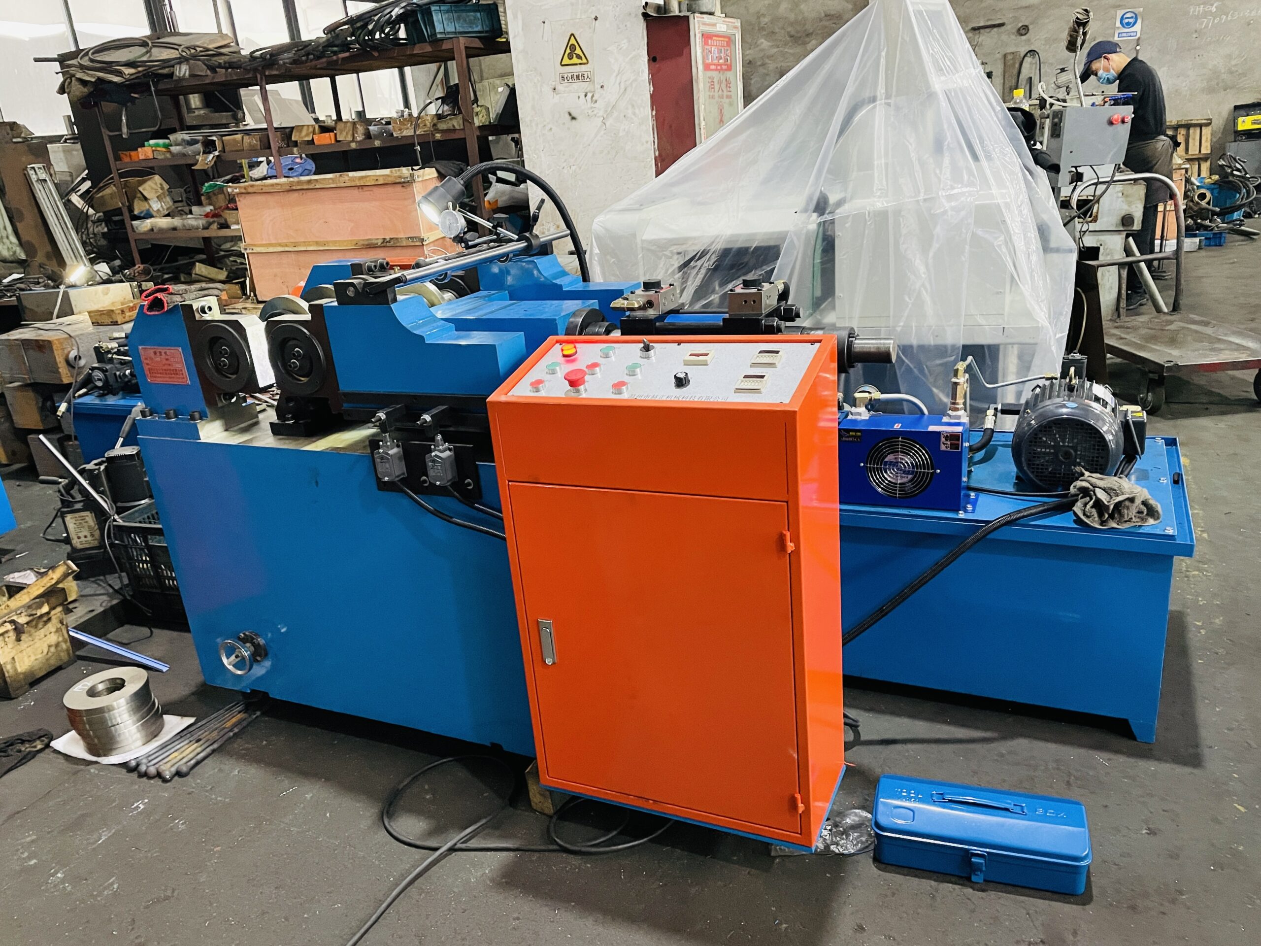
Foto projek mengesahkan mesin jenis roller, panduan dan kawasan ukuran. Ia tidak membuktikan kiraan roller tertentu, kawalan gelung tertutup automatik, kelajuan atau ketepatan.
Proses Meluruskan Roller yang Disyorkan
1. Kenal pasti varian dan peringkat yang diluluskan
Pengendali memilih resipi untuk penempaan yang tepat, panjang, diameter batang, keadaan kekerasan dan keadaan permukaan. Bahagian bercampur atau peringkat pembuatan yang salah dihalang daripada memasuki set roll.
2. Periksa kosong yang masuk
Bahagian yang retak, lipatan, kerosakan kepala yang teruk, selekoh atau dimensi berlebihan di luar tetingkap yang disahkan dipisahkan sebelum diluruskan. Meluruskan bukan kaedah pembaikan untuk menempa kecacatan.
3. Orientasikan dan bimbing kepala bola
Panduan kemasukan memastikan stud stabil sambil membenarkan zon shank yang diluluskan memasuki gulungan. Kepala bola dan peralihan kekal di luar sentuhan garisan berbahaya. Jika bahagian itu termasuk rumah pangsa, kesannya pada putaran dan penyusuan disahkan.
4. Gunakan tetapan roller yang disahkan
Profil gulung, sudut silang, jurang/tekanan, kedudukan panduan dan kelajuan suapan dikawal resipi. Tetapan mesti mencipta pembetulan plastik yang mencukupi dalam batang tanpa perubahan diameter yang berlebihan, menggilap, lekukan, kenaikan suhu atau risiko tekanan sisa.

5. Ukur menggunakan datum yang dipersetujui
Bahagian diukur pada stesen dan orientasi yang ditentukan. Bergantung pada lukisan, ini boleh menjadi pemeriksaan dalam mesin, tolok luaran, profil optik atau ujian runout berasaskan putaran. Susunan penunjuk yang boleh dilihat dalam foto menyokong aktiviti pengukuran, bukan tuntutan pemeriksaan akhir automatik.
6. Tentukan lulus, memproses semula atau menolak
Satu pas tambahan dibenarkan hanya apabila disertakan dalam resipi yang disahkan. Gulungan berulang tanpa had boleh mengubah keadaan permukaan, diameter dan tegasan sisa. Bahagian di luar tingkap yang diluluskan dikuarantin untuk semakan kejuruteraan.
7. Sahkan keadaan serta geometri
Pelan kualiti boleh termasuk pemeriksaan permukaan, semakan dimensi, zarah magnetik atau pemeriksaan retak lain, pengesahan kekerasan dan ujian pemesinan/pemasangan hiliran. Kaedah yang tepat mengikut bahan, peringkat pembuatan dan lukisan pelanggan.
Video Meluruskan Stud Bola Panjang Sebenar
Video awam berikut dikaitkan dengan artikel stud bola panjang asal dan menunjukkan peralatan meluruskan roller projek. Ia menyokong konsep proses yang boleh dilihat sahaja. Ia tidak membuktikan yang dinyatakan sebelum ini 0.2 keputusan mm, 20–45 julat HRC, pelanggan India, peningkatan pengeluaran atau penilaian pelanggan.
Meluruskan Roller atau Pembetulan Titik Terukur?
| Faktor keputusan | Meluruskan penggelek mungkin lebih disukai apabila | Pembetulan mata mungkin lebih disukai apabila |
|---|---|---|
| Pengagihan bengkok | Kelengkungan diedarkan di sepanjang batang seragam | Satu atau lebih titik tinggi setempat boleh diukur |
| Zon hubungan | Sentuhan batang berterusan dibenarkan | Hanya zon sokongan dan akhbar terpilih sahaja dibenarkan |
| geometri tamat | Head dan ciri lain boleh mengosongkan sistem roll/panduan | Hujung kompleks menjadikan laluan berterusan tidak selamat |
| Permukaan | Sentuhan penggelek dan sebarang kesan penggilapan boleh diterima | Permukaan siap memerlukan perkakas terlindung setempat |
| Pengukuran | Pemeriksaan sebelum/selepas atau sampel adalah mencukupi | Pengukuran gelung tertutup selepas setiap pembetulan diperlukan |
| Bahagian campuran | Stabil, keluarga volum lebih tinggi | Bahagian volum rendah atau campuran tinggi dengan resipi khusus |
Kedua-dua kaedah tidak "terbaik" secara universal. Satu kajian sampel juga boleh menunjukkan bahawa meluruskan harus dipindahkan ke peringkat pembuatan yang lebih awal daripada memaksa stud bola siap melalui salah satu proses.
kepala, Peralihan dan Perlindungan Permukaan
| risiko | Kawalan |
|---|---|
| Permukaan bola lekuk atau calar | Kosongkan bola daripada gulungan yang berfungsi dan gunakan panduan yang diluluskan |
| Retak peralihan | Kecualikan jejari daripada pemuatan tertumpu; tambah pemeriksaan retak yang diperlukan |
| Lekukan batang atau perubahan diameter | Profil gulungan perlawanan, tekanan dan keadaan permukaan; ukur selepas diproses |
| Rata atau benang menangkap panduan | Tentukan orientasi/pelepasan dan gunakan alatan khusus varian |
| Kerosakan lapisan mengeras | Sahkan tekanan sentuhan dan had pembetulan pada sampel setara pengeluaran |
| Terlalu panas atau menggilap berlebihan | Hadkan kelajuan/tekanan/laluan dan pantau syarat yang dipersetujui |
| Bahagian keluar tanpa diduga | Gunakan panduan positif, menjaga dan pengumpulan yang selamat |
Contoh Pelan Ujian dan Penerimaan
Sampel perwakilan
- panjang sentuhan roller terpendek yang boleh digunakan dan nisbah kepala ke batang terbesar;
- diameter batang minimum dan maksimum;
- setiap keadaan penempaan dan rawatan haba yang berkaitan;
- setiap flat, tirus, konfigurasi benang dan hujung;
- bahagian merentasi pengedaran selekoh masuk sebenar;
- berbilang kelompok di mana skala penempaan, kekerasan atau springback boleh berbeza-beza.
Bukti yang diperlukan
| Rekod | Bukti penerimaan |
|---|---|
| Bahagian identiti | Semakan lukisan, varian, bahan, peringkat dan kumpulan |
| Geometri masuk | Ciri, datum, jawatan dan nilai |
| resepi | gulung, panduan, jurang/tekanan, sudut, had laju dan hantaran |
| geometri akhir | Ciri yang ditakrifkan sama serta korelasi tolok pelanggan |
| Dimensi | Diameter tangkai dan ciri fungsi kekal dalam toleransi |
| Permukaan/peralihan | Hasil pemeriksaan visual dan retak yang diluluskan |
| Percubaan pengeluaran | Kitaran yang diukur, jem, tukar ganti, pemeriksaan dan ketersediaan |
Kajian mesti merangkumi bahagian berhampiran sempadan proses yang dimaksudkan, bukan sahaja beberapa sampel mudah.
Skop Automasi
| Tahap | Skop biasa |
|---|---|
| Manual | Beban operator, menjalankan pas yang diluluskan dan memunggah untuk pemeriksaan |
| Dibantu | Sokongan infeed/outfeed dan koleksi berpandu |
| Automatik | Perpisahan, orientasi, bergolek, pengukuran dan pengisihan hasil |
| Boleh dikesan | Identiti bahagian/lot, resepi, rekod pengukuran dan proses |
Pemuatan automatik bergantung pada sama ada kepala bola kusut, sama ada flat atau tirus memerlukan orientasi dan sama ada sentuhan permukaan dibenarkan. Automasi dan kebolehkesanan adalah skop yang dipesan, bukan andaian daripada gambar mesin.
Apa yang Bukan Janji Sejagat
Sebelum semakan lukisan dan pengesahan sampel, penyelesaian ini tidak menjanjikan:
- 0.2 mm kelurusan untuk ciri yang tidak ditentukan;
- satu tetingkap proses untuk setiap 20–45 bahagian HRC;
- kesesuaian untuk sambungan bola yang dipasang atau rod seri yang lengkap;
- sentuhan roller selamat pada bola siap, tirus, benang atau salutan;
- satu tetapan penggelek untuk semua panjang dan diameter;
- sifar retak, markah, perubahan diameter atau kesan tekanan baki;
- masa kitaran tetap, peningkatan output atau pengurangan kos;
- keputusan atau testimoni pelanggan India tanpa rekod yang dibenarkan.
Aplikasi Berkaitan
Semak semula kami Penyelesaian Pengikat dan Pelurus Alat dan Mesin Meluruskan Stud Bola untuk konteks aplikasi dan peralatan bersebelahan. Jika komponen mempunyai rak stereng atau fungsi batang pengikat yang dipasang, ia memerlukan kajian datum dan risiko fungsian yang berasingan.
Maklumat untuk Dihantar untuk Cadangan
Most long ball stud straightening enquiries move faster when the buyer arrives with the panduan pemilihan mesin untuk aci, tiub dan profil already worked through and a target range from the pecahan harga untuk mesin pelurus.
Hantar lukisan dan semakan, sampel perwakilan, dimensi bola / batang / peralihan, perincian flat/tirus/benang, bahan dan laluan rawatan haba, peringkat pembuatan yang tepat, keadaan permukaan, pengagihan selekoh masuk, ciri akhir dan datum, tolok pelanggan, zon hubungan terlarang, keperluan pemeriksaan retak, sasaran output dan kaedah pemuatan pilihan.
Hubungi StraighteningTech untuk kajian meluruskan stud bola panjang berasaskan sampel. Kami akan menentukan peringkat proses yang sesuai, konsep penggelek atau pembetulan titik, zon terlindung, kaedah pengukuran dan bukti penerimaan untuk keluarga bahagian sebenar.
Soalan Lazim
Adakah stud bola sama dengan rod seri?
Tidak. Stud bola ialah komponen di dalam sendi bola. Batang pengikat ialah pautan stereng yang lebih besar yang biasanya merangkumi sambungan bebola dan sambungan pelaras. Penyelesaian ini melibatkan kosong atau bahagian stud bola panjang individu.
Bolehkah kepala bola melepasi antara gulungan pelurus?
Bukan secara lalai. Bola dan peralihannya berfungsi, zon yang sarat tinggi. Perkakas biasanya membersihkan atau membimbing mereka semasa batang seragam yang diluluskan memasuki gulungan. Sebarang hubungan langsung memerlukan kelulusan lukisan yang jelas dan pengesahan sampel.
Boleh bahagian mengeras ke 45 HRC diluruskan?
Mungkin untuk bahan tertentu, profil kekerasan, geometri dan selekoh masuk, tetapi bilangannya sahaja tidak mencukupi. Springback, kedalaman kes, tekanan peralihan, risiko retak dan sentuhan permukaan yang dibenarkan mesti diuji.
Adakah 0.2 mm keperluan kelurusan atau kehabisan?
Nombor sahaja tidak boleh menjawabnya. Lukisan mesti menamakan ciri, panjang terkawal, datum, kedudukan pengukuran dan kaedah penilaian. Mesin dan tolok pelanggan kemudiannya memerlukan kajian korelasi.
Bilakah pembetulan mata perlu dipertimbangkan sebaliknya?
Apabila selekoh disetempat, panjang sentuhan roller yang boleh digunakan adalah pendek, ciri kompleks menghalang laluan berterusan yang selamat atau permukaan siap memerlukan perkakas terpilih dan ukuran gelung tertutup.
Sempadan Rujukan Teknikal
- Sendi Bola ZF: https://press.zf.com/press/en/media/media_2252.html
- Batang Pengikat ZF: https://www.zf.com/products/en/cars/products_65853.html
- Bahagian Stereng dan Casis ZF: https://aftermarket.zf.com/sg/aftermarket-portal/our-portfolio/passenger-cars/products/steering-and-chassis-parts/
- Sendi Bola MOOG: https://www.moogparts.com/en-eu/products/suspension/ball-joints.html
- Mesin Meluruskan Danieli: https://www.danieli.com/en/products/products-processes-and-technologies/ingot-casting_26_12.htm
- Mesin Meluruskan Dua Gulungan Mair Research: https://www.mair-research.com/en/two-roll-straightening-machine/
- Bahan Kerja dan Aplikasi MAE: https://mae-group.com/ms/workpieces-applications/
Rujukan ini menyokong terminologi sendi bola, kepelbagaian keadaan bahan dan prinsip penggelek/pelurus tekanan umum. Mereka tidak membuktikan bahawa prestasi pembekal lain terpakai pada konfigurasi StraighteningTech.