
Welding wire is manufactured, shipped and fed as coil, but a significant part of the market is consumed as straight lengths: TIG rods cut from hard wire, plasma and laser cutting wire, stud welding feed stock, and nickel-alloy filler supplied in straightened bars. Between the coil and the straight length stands a straightening and cutting operation whose quality shows up later in two places — the straightness of the cut rod on the welding bench, and the cast and helix behavior of the wire as it feeds through a robotic torch. Both are straightening problems, and they are different ones.
A welding wire straightening solution has to answer five questions first:
- Is the product straight cut lengths from coil, or controlled cast and helix on spooled wire?
- Which wire family — carbon steel hard wire, kowiri, konumohe, flux-cored, or nickel filler?
- What straightness does the downstream user actually require over what cut length?
- Which straightening mechanism fits the line speed and the wire’s sensitivity to tooling marks?
- How will cast, helix and length accuracy be sampled and verified in production?
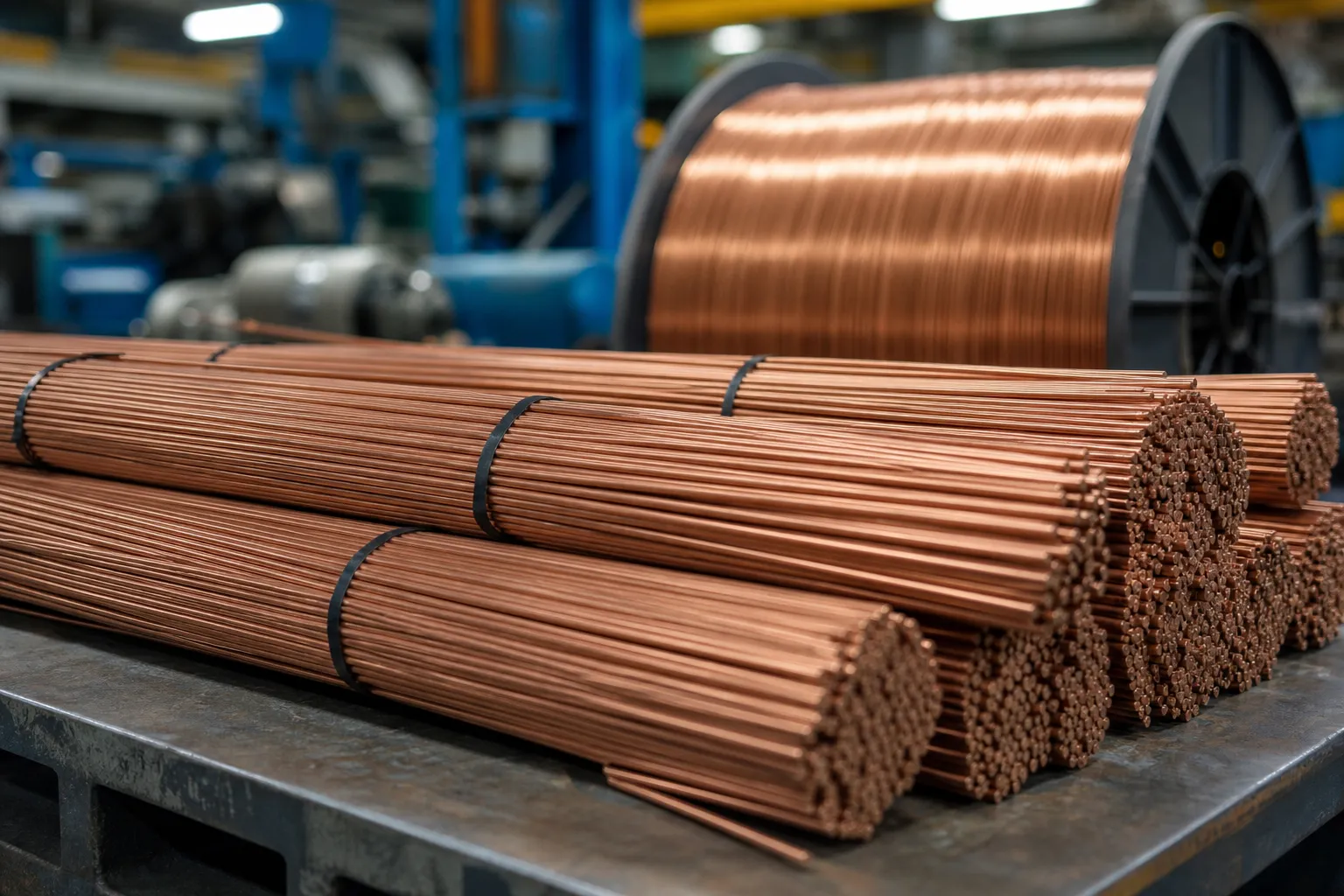
*Whakaahua aria hangarau: straightened welding wire cut lengths staged in bundles. Ehara i te whakaahua-paetukutuku. Straightness values, cut length tolerances and machine configuration follow product specifications and sample tests.*
What the Search Results Mix Together
Search results for welding wire straightening are dominated by a different problem than the one this page solves. Most visible results address the welding cell: inline wire straighteners mounted ahead of the torch, accessory catalogs from welding-equipment makers, and forum threads about wire that curls out of the contact tip. Those devices tune the wire’s residual cast inside a feeding system — a legitimate topic, but an end-user one.
This page is written from the production side: the wire mill or cut-length processor that takes layer-wound coil and produces straight product. Equipment builders such as WAFIOS and Clifford produce straighten-and-cut lines of exactly this type, and the engineering questions — mechanism choice, cast control, tohu taputapu, cut accuracy — are decided here, not at the welding bench.
Two Adjacent Problems on This Site
Two existing guides border this one. Ko te fine stainless steel wire straightening and cutting solution covers very fine diameters where the mechanism and handling dominate. Ko te te hurihuri me te waea hurihuri comparison works through the two straightening mechanisms in detail. Neither addresses what makes welding wire specific: the cast-and-helix acceptance language of the welding industry, the flux-cored constraint, and the way cut-length product is graded. Those are this page’s subject.
Welding Wire Families Behave Differently
| Wire Family | Typical Product | Te Whakaaro Whakatika |
|---|---|---|
| Carbon steel hard wire (e.g., ER70S-6 class) | TIG cut rods, stud welding stock, cut lengths | High volume; copper coating must survive tooling |
| Stainless wire (308L/309L/316L class) | TIG rods and straightened bar stock | Work-hardening behavior; surface finish sensitivity |
| Aluminum wire | Straight lengths for specialized processes | Ngohe; marks easily; low correction force needed |
| Flux-cored wire | Coil product with cast and helix acceptance | Seam must never see crushing tooling contact |
| Nickel and alloy filler | Straightened bars for high-alloy welding | Te kaha teitei ake; premium product economics |
Cast and Helix: The Vocabulary That Decides Acceptance
Welding suppliers describe spooled wire quality with two quantities. Cast is the diameter of the circle a cut sample naturally forms when free on a flat surface. Helix is the axial rise of that circle — how much the sample climbs out of the plane per turn. Robotic-welding torch manufacturers publish guidance on both because excessive cast or helix drives contact-tip wear, TCP deviation and erratic arc positioning. These are not cosmetic numbers; they are the functional definition of “tika” for wire that must feed through a delivery system.
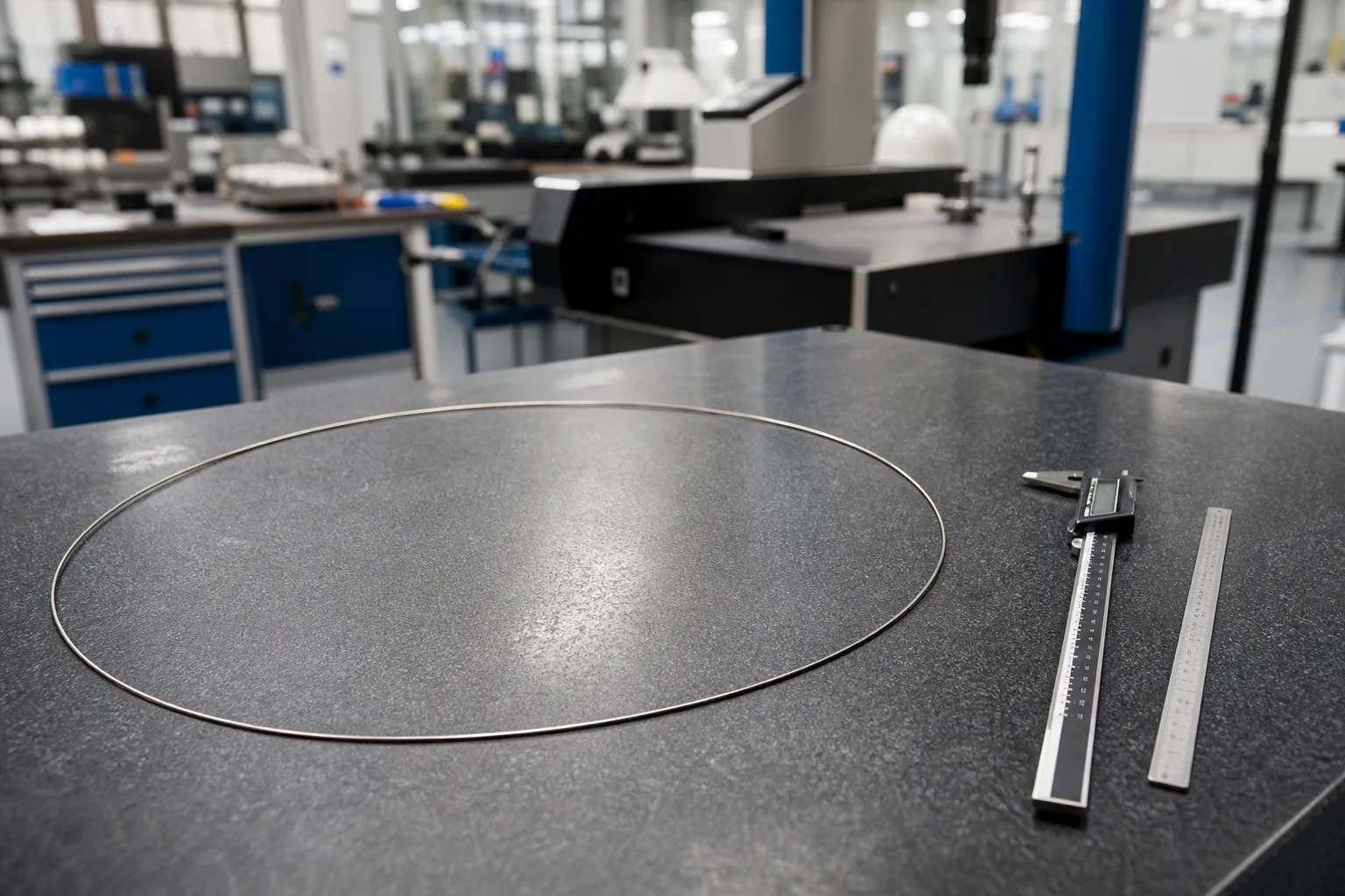
*Whakaahua aria hangarau: a free-lying wire sample revealing its cast diameter and helix rise. The acceptance values belong to the product specification; the measurement method belongs to the quality plan.*
For straight cut-length product, the equivalent acceptance is simpler to state but harder to hold over length: chord height or deviation from straight over the full cut length, sampled across the bundle. A rod straight at 300 mm and bowed at 1200 mm is a different product, and the difference traces back to residual stress left by the straightening mechanism.
The Production Chain and Where It Goes Wrong
Straight cut lengths run through a fixed sequence: payoff from layer-wound coil or spool, whakatikatika, cutting to length, then bundling or boxing. Distortion enters at identifiable points:
- Coil memory. Wire drawn and wound with residual stress will not lie straight without mechanical correction — the payoff geometry sets the initial bend conditions the straightener must undo.
- Ka mutu- or under-straightening. Too little correction leaves cast; too much drives reverse curvature and work-hardens the wire, me te “tika” rod becomes a spring that moves when cut. Delivering a stable result through the elastic recovery is a compensation problem of the same family as the springback compensation logic in shaft straightening.
- Tooling marks. Nicked or misaligned rolls and dies leave longitudinal scoring that users of polished stainless rod see immediately — the general principles are covered in the surface-protection tooling guide.
- Cut-length error. Slip between the feeding rolls and the shear at line speed turns a straight product into a wrong-length product.
- Post-cut handling. Straight rods are re-bent in bins; bundling and box design are part of the quality system, ehara i te whai whakaaro.
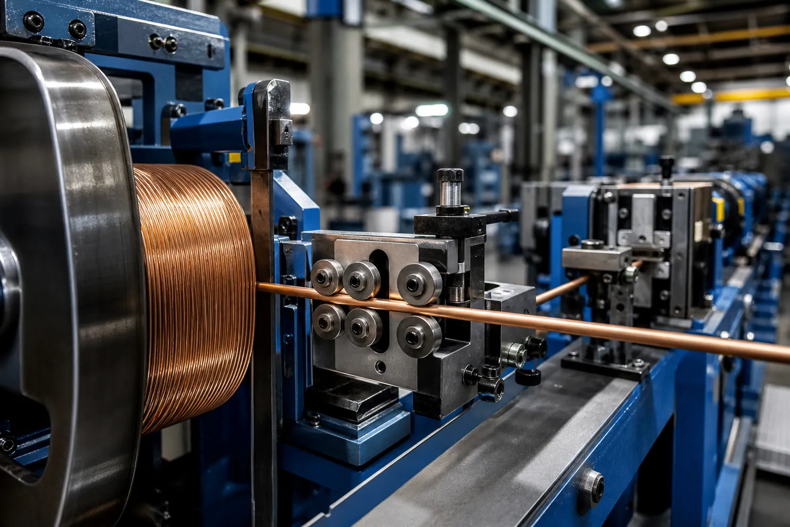
*Whakaahua aria hangarau: payoff, straightening and cutting arranged as one synchronized line. Roll count, rotary-die choice and shear type follow wire diameter and line speed.*
Choosing the Mechanism
The full comparison of roll straightening and rotary-die straightening — the two established mechanisms — is the subject of the te hurihuri me te waea hurihuri aratohu. In summary for welding product: roll straighteners contact the wire in a fixed plane and their setting directly shapes the cast you deliver; rotary straighteners spin the correction around the axis and are often preferred where helix control matters. Flux-cored wire narrows the choice further, because the seam side of the wire cannot tolerate the concentrated contact some tooling applies — a constraint that has to be engineered around, not discovered in production.
Aluminum and the Soft-Wire Exception
Aluminum welding wire changes the engineering conversation. The correction force is small, the damage threshold is smaller, and any tooling mark that would be invisible on hard-drawn carbon steel is a visible defect on a soft, bright surface. Feeding behavior is also less forgiving: aluminum’s cast and helix tolerance in delivery systems is tighter in practice, and the wire’s low stiffness means payoff geometry and guide alignment contribute to the final cast as much as the straightener itself. Lines that run both steel and aluminum product carry this as a changeover discipline — separate tooling sets, separate settings, separate sampling.
Where Wire Ends and Bar Begins
Welding wire tops out where straightened bar products begin. Above roughly the largest welding-wire diameters, the product is no longer paid off coil but sawn or drawn bar, and the machinery changes with it — the long steel bar roller straightening solution covers that territory. The border matters for equipment planning: a wire line stretched beyond its diameter range delivers neither good wire nor good bar.
Tukatuka Kati-Koropiko
- Fix the product definition: wire family, diameter, cut lengths, acceptance for cast, helix and straightness.
- Qualify incoming coil: supplier, winding geometry, visible cast per spool.
- Set payoff geometry and tension limits.
- Configure the straightening mechanism and record settings per product.
- Run samples; measure free-lying cast and helix, and chord deviation over full cut length.
- Adjust until the acceptance is met with margin, not at the limit.
- Cut to length; verify length distribution at speed.
- Inspect surface for tooling marks; flux-cored product gets seam inspection.
- Bundle and box in a way that preserves the delivered geometry.
- Record settings and measurement results per lot for traceability.
Aratau Rahunga noa
The recurring mistakes: copying straightener settings from one wire family to another and delivering reversed cast; grading the product by eye instead of a free-lying sample; sampling straightness only at the mid-point of the cut length; ignoring the payoff side and fighting coil memory entirely inside the straightener; and shipping straight rods in packaging that bends them before they reach the customer. Each of these is a process-definition error, not a machine-capability error — which is why the proposal stage matters.
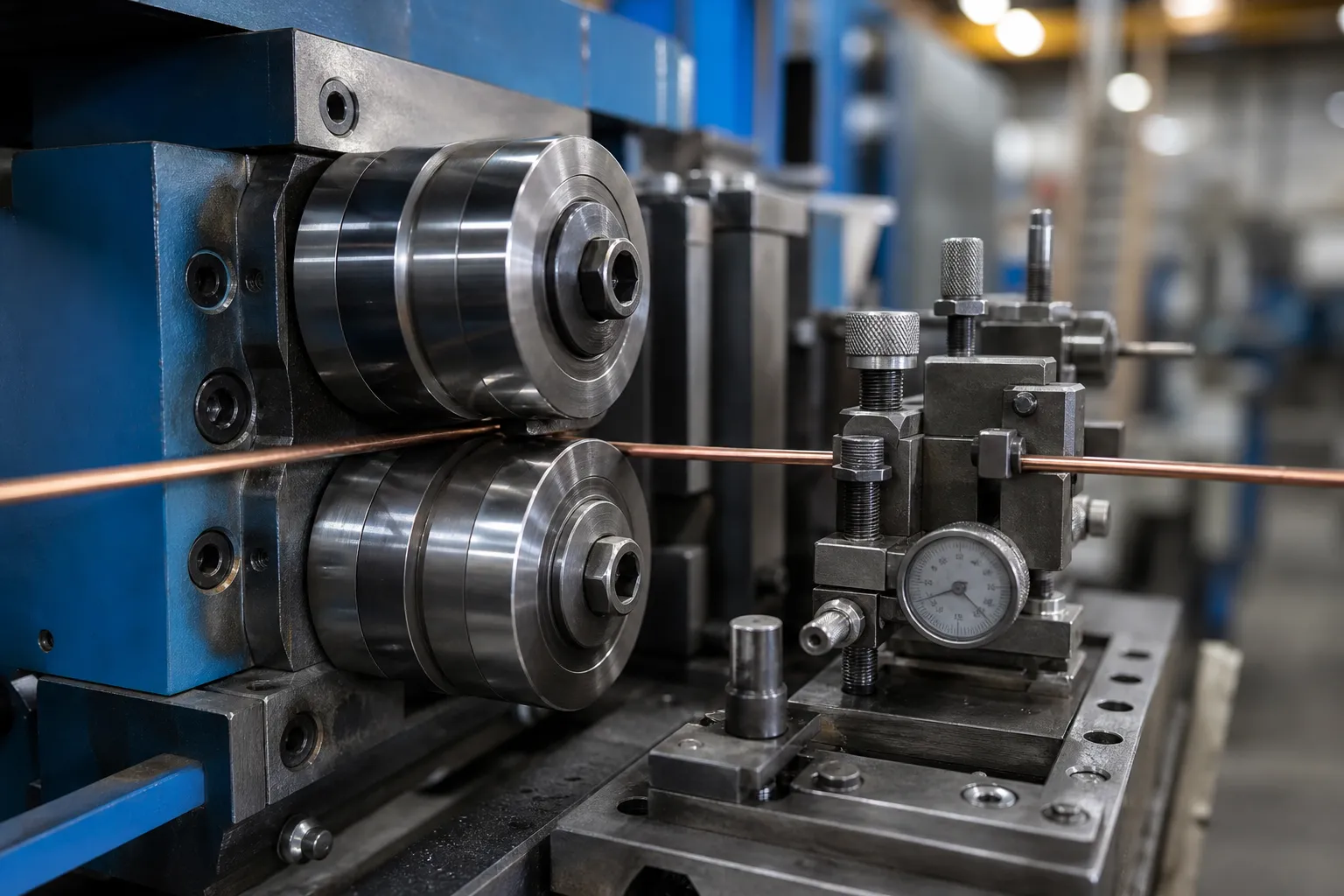
*Whakaahua aria hangarau: the straightening tooling block where roll condition and settings determine both the delivered cast and the surface quality of the product. Roll materials and geometries follow the wire family.*
Raraunga e Hiahia ana mo te Tono Hangarau
- wire family, grade and diameter range;
- product form: cut lengths, straightened bar, or controlled-cast spool;
- cut lengths and length tolerance;
- acceptance criteria for cast, helix and straightness;
- incoming coil format and supplier winding standard;
- required line speed and hourly output;
- surface and coating constraints (copper coating, polish, flux seam);
- lot sizes and changeover frequency between products;
- measurement and sampling plan expectations;
- packaging and bundling requirements;
- representative coil samples for trials.
Pātai Auau
What is cast in welding wire?
Cast is the diameter of the circle a freed wire sample forms on its own. Welding-industry guidance treats cast and helix as feedability characteristics — excessive values degrade robotic torch performance even when the wire looks acceptable on the spool.
Can curly wire from a spool be straightened at the welder?
Inline straighteners ahead of the torch adjust residual cast inside the feeding system, and that end-user question dominates general search results. It is distinct from producing straight wire at the mill, which is what this page and the equipment behind it address.
Roll or rotary straightening for welding wire?
Both are used. Roll straightening shapes cast through fixed-plane contact and suits many hard-wire products; rotary straightening wraps correction around the axis and tends to suit helix-sensitive product. The detailed trade-offs are compared in the roll vs rotary guide, and flux-cored wire adds seam-contact constraints to either choice.
Can flux-cored wire be straightened like solid wire?
Not identically. The flux seam limits acceptable tooling contact geometry and force concentration, so the mechanism and tooling must be selected around the seam — a constraint that belongs in the specification, not in a workaround.
Why do straightened rods bend again after cutting?
Te ahotea toenga. Over-straightened wire stores elastic energy that releases when the continuous wire becomes a free rod. The correction is a straightening setup that reaches acceptance with margin rather than at the limit, verified by sampling the cut product — not the wire still under tension in the line.
From Coil Memory to a Straight Product
We build welding wire straightening and cutting solutions around the wire family, the cast-and-helix acceptance language of the welding industry, the mechanism choice between roll and rotary straightening, tooling that does not mark the product, and a sampling plan that verifies the cut rod rather than the wire under tension. Tukuna te tohu waea, awhe diameter, cut lengths, acceptance criteria and line-speed expectations, and we will define the straightening configuration, tooling plan and verification method for your welding wire product.