
Vökvakæligreinir dreifa kælivökva í gegnum rafhlöðuna, gagnaver, rafeindatækni eða iðnaðarvarmastjórnunarkerfi. Langur holur snið þeirra, soðin tengi og þéttingarskil verða að vera rúmfræðilega stöðug þannig að samsetningin passi í kælikerfið án þess að þvinga, lekahætta eða jöfnunarvandamál.
Þessi fyrirhugaða lausn er byggð á 304L ryðfríu stáli rétthyrndu holu sundrið sem mælist u.þ.b. 78 mm breiður, 45 mm hár og 1800 mm langur, með a 3 mm vegg. Viðskiptavinurinn greinir frá tveimur mismunandi aflögunarstigum: aðkomandi slönguendarnir geta verið snúnir um u.þ.b 20 mm, og suðu kynnir aðra beygjuaflögun. Þetta eru mismunandi gallar og ætti að meðhöndla þær með aðskildum sléttunaraðferðum frekar en einni almennri pressulotu.

Vinnustykki og kröfur viðskiptavina
Greinið byrjar sem langt ferhyrnt hol rör og tekur síðar við mörgum greinum, port eða soðnar festingar. Viðskiptavinurinn leiðréttir upphafssnúninginn handvirkt, tekur um 30 mínútur á hluta. Eftir snúningsleiðréttingu, hluturinn er soðinn og gæti bognað aftur, búa til aðra réttingarkröfu fyrir lokasamsetningu eða lekaprófun.
Uppgefið framleiðslumagn er 12,000 hlutar á mánuði og umbeðin nákvæmni eftir réttingu er 0.15 mm. Áður en þetta gildi verður búnaðarábyrgð, teikningin verður að skýra hvort hún stjórnar beinu stigi, flatneskju, prófíl, endastöðu, hafnarstöðu eða annað rúmfræðilegt einkenni, og yfir hvaða datum lengd það er mælt.
| Verkefni | Inntak viðskiptavina / Staða |
|---|---|
| Vinnustykki | Vökvakæligrein / dreifiþætti |
| Efni | 304L ryðfríu stáli |
| kafla | Rétthyrnd holur snið, um það bil 78 × 45 mm |
| Veggþykkt | 3 mm |
| Lengd | Um það bil 1800 mm |
| Upphafsgalli | Tube-enda snúningur tilkynntur um kl 20 mm |
| Annar galli | Beygja eftir suðu |
| Núverandi aðferð | Handvirk leiðrétting á snúningi, um það bil 30 mín/hluti |
| Framleiðslumagn | 12,000 hlutar/mánuður |
| Umbeðin nákvæmni | 0.15 mm; einkenni og viðmiðun til að staðfesta |
| Tillaga að lausn | Snúningsleiðréttingarbúnaður auk beygjuréttingarvélar |
Snúningur og beygja þarf að mæla sérstaklega
Snúningur þýðir að einn þverskurður hefur snúist miðað við annan eftir lengd sniðsins. Beygja þýðir að lengdarmiðlína eða viðmiðunarflöt víkur frá tilskildri línu. Fjölgrein getur verið beint í hliðarsýn en samt haft snúna enda, eða það getur haft rétta endastefnu við hneigð eftir suðu.
Að nota aðeins lóðrétta tilfærslunema getur ekki lýst snúningsvillu að fullu. Snúningsstöðin þarf hyrndar- eða fjölflatamælingu á rétthyrndu sniðinu eða endapunktum. Beygjuréttastöðin þarf línulegar mælingar meðfram samþykktum viðmiðunarflötum eða miðlínu. Port- og flansstaða gæti krafist viðbótarmæla ef þeir eru virkir samþykkiseiginleikar.
| Galli | Dæmigerð mæling | Nauðsynleg leiðrétting |
|---|---|---|
| Enda snúningur / snúningur | Hornasamanburður á endaþversniðum, margyfirborða rannsaka, leysir eða innréttingarmælir | Stýrð mótvægis- eða snúningsrétting |
| Lóðrétt boga | Færslumæling meðfram efsta/neðsta viðmiðinu | Lóðrétt fréttaleiðrétting |
| Lárétt boga | Hliðarmæling meðfram viðmiðunarflati eða miðlínu | Lárétt leiðrétting eða endurstilling |
| Staðbundin suðubjögun | Mæling nálægt soðnum höfnum eða hitaáhrifasvæðum | Staðbundin punktaleiðrétting með álagsmörkum |
| Höfn / passa misskipting | Innrétting, sýn, CMM eða sérstakur hagnýtur mælir | Aðskilið samþykki eða staðbundin leiðrétting ef hún hefur verið staðfest |
The 0.15 Ekki er hægt að úthluta mm kröfu til allra þessara eiginleika án þess að draga fram sannanir. Hver stýrður eiginleiki ætti að hafa sitt eigið viðmið, mælistöðu og OK/NOK regla.
Hvers vegna er erfitt að rétta úr vökvakælibúnaði
The 3 mm holur veggur skapar hættu á klemmu, inndráttur eða staðbundin buckling undir einbeittum stuðningi eða snertingu við pressu. Rétthyrnd þversniðið hefur mismunandi stífleika um aðal- og smáása sína, þannig að sama þrýstihöggið framkallar mismunandi viðbrögð eftir stefnu. The section-preservation logic for smaller hollow parts is covered in þunnveggja rörrétting.
Suðar gera viðbragðið enn minna einsleitt. Hitainntak og suðuröð geta dregið greinina í átt að soðnu hliðinni, á meðan margar hafnirnar skapa staðbundnar stífleikabreytingar. Að ýta á port, suðuperla, þéttiflöt eða þunnur óstuddur veggur getur skemmt hagnýtan eiginleika. Ferlið verður því að nota útlínur stuðning og pressuverkfæri staðsett á milli eða í kringum mikilvæga eiginleika.
| Áskorun | Áhætta | Verkfræðieftirlit |
|---|---|---|
| 1800 mm langt snið | Sjálfsþyngd og óstöðug mæling | Dreifðar stoðir og mælingar í fullri lengd sem byggja á datum |
| 3 mm holur veggur | Myljandi eða varanleg inndráttur | Breiða útlínur verkfæri, innri stuðningur þar sem þörf er á, afl/höggmörk |
| Rétthyrndur hluti | Mismunandi stífleiki eftir stefnu | Aðskilið lóðrétt, láréttar og snúningsuppskriftir |
| Um 20 mm enda snúningur | Ekki er hægt að fjarlægja það á áreiðanlegan hátt með einfaldri lóðréttri pressu | Sérstök snúningsstöð og hyrnd endurgjöf |
| Margar soðnar tengi | Staðbundin stífni og hitaaflögun er mismunandi eftir lengd | Gerðarsértæk pressusvæði og staðbundin mæling |
| 12,000 hlutar/mánuður | Handvirkt 30 mínútna ferli getur ekki stutt áskilið úttak | Sjálfvirk meðhöndlun, samhliða aðgerðir og takt-tíma sannprófun |
Mælt er með tveggja þrepa sléttunarhugmynd
Ákjósanleg hugmynd aðskilur leiðréttingu á snúningi fyrir suðu frá beygjuleiðréttingu eftir suðu. Fyrsta stöðin tekur á móti rétthyrndu rörinu eða forsamsetningu, staðsetur báða endana og mælir hlutfallslega hornskekkju. Stýrður snúningsstýribúnaður eða gagnstæðar klemmur beita mótvægi í staðfestum þrepum, fylgt eftir með endurmælingu.
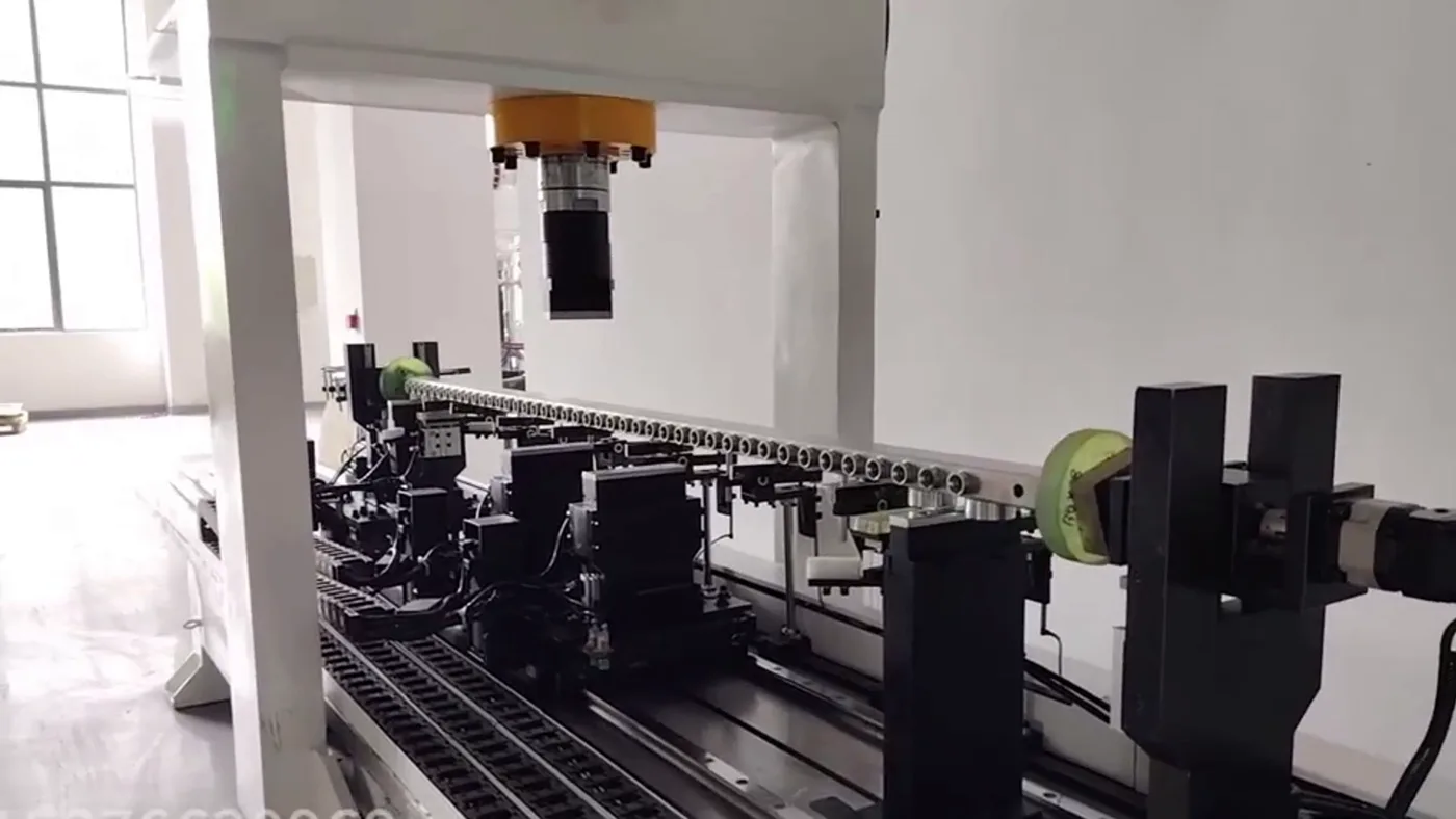
Eftir suðu, sundrið fer inn í langbeðs punktréttunarstöð. Margir stuðningur ákvarða viðmiðið, skynjarar kortleggja beygjuna eftir endilöngu, og hreyfanleg eða verðtryggð pressa beitir stýrðri leiðréttingu á viðurkenndum stöðum. Verkefnismyndbandið sýnir þetta langa margþætta pressuréttingarhugtak; það sýnir hvorki né sannar aðskildu forsuðu snúningsleiðréttingarstöðina.
Sviði 1: Forsuðu leiðrétting
Skref 1: Þekkja sniðið og koma á lokadagsetningum
Festingin staðsetur rétthyrnd rörið með því að nota samþykkta viðmiðunarflöt eða endaþætti. Klemmur verða að dreifa snertingu yfir 3 mm vegg án þess að skapa beyglur. Ef hluturinn inniheldur þegar viðkvæmar festingar, þessi svæði eru áfram utan klemmasvæðisins.
Skref 2: Mældu upphafssnúninginn
Kerfið ber saman hornstefnu beggja endanna eða nokkurra þverskurða. Tilkynnt „20 mm snúning“ ætti að breyta í skilgreinda rúmfræðilega mælingu - svo sem endahornsfærslu við þekktan mæliradíus eða horngráður - þannig að stjórnkerfið og skoðun viðskiptavina noti sömu skilgreiningu.
Skref 3: Notaðu stjórnað mótvægi
Einum endanum er haldið á meðan hinum er snúið í gagnstæða átt með því að nota stjórnað tog eða hornfærslu. Vegna þess að 304L ryðfríu stáli fjaðrar aftur, stöðin þarf staðfesta yfirsnúningastefnu. Hámarks tog, horn- og leiðréttingarlotur vernda hola hlutann og alla soðna sauma.
Skref 4: Endurmældu og samþykktu forsuðuhlutann
Hluturinn er endurmældur eftir hverja leiðréttingu. Aðeins snið innan samþykktra torsionsmarka fyrir suðu halda áfram í suðu. Skráning á komandi og leiðrétta snúningi getur einnig leitt í ljós vandamál í túpunni, geymslu eða andstreymismyndun.
Sviði 2: Beygjurétting eftir suðu
Skref 1: Hlaðið og styðjið soðið margvíslegan
Fullbúna eða hálfgerða greinarkerfið er sett á dreifðar stillanlegar stoðir. Festingin verður að gera grein fyrir langa líkamanum, margar hafnir og mismunandi endabyggingar á sama tíma og það gefur skýran aðgang fyrir skynjara og pressuhausinn.
Stuðningspunktar ættu að hafa samband við viðurkenndan breið yfirborð. Hafnir, suðuperlur, þéttingarfletir og þunnir óstuddir veggir eru skilgreindir sem verndarsvæði. Contact-zone validation follows the same yfirborðsverndarverkfæri rules.
Skref 2: Kortleggja aflögun af suðu
Hafðu samband við rannsaka, leysiskynjarar eða samsetning mæla viðeigandi viðmiðunarflöt á mörgum stöðum. Stýringin greinir heildarbogann frá staðbundinni aflögun nálægt suðu. Ef bæði lóðrétt og lárétt beygja er stjórnað, kerfið þarf mælingar í báðar áttir eða staðfesta hluta-endurstefnuröð.
Skref 3: Reiknaðu frétta- og stuðningsstöður
Stýringin auðkennir beygjutoppinn og velur öruggan leiðréttingarpunkt á milli mikilvægra hafna. Stífleiki staðbundinnar hluta, fjarlægð að næstu suðu og burðarspenna hafa áhrif á upphafshöggið. Stefnan verður að forðast einfaldlega að ýta á stærsta mælda frávikið þegar þessi staðsetning er veikt eða virkt svæði.
Skref 4: Notaðu stjórnaða stuttleiðréttingu
Pressan beitir takmörkuðu yfirbeygjuslagi til að vega upp á móti bakslagi. Breið útlínur verkfæri dreifir álagi yfir rétthyrndu rörið. Þar sem hættan á hruni er mikil, innri dorn, staðbundin fylliefni eða sérhæfður utanaðkomandi stuðningur gæti þurft eftir verkfræðiskoðun.

Þróa skal kraft- og tilfærslumörk úr dæmigerðum soðnum sýnum. Skyndileg breyting á kraft-tilfærslu svörun getur bent til rangs stuðnings, annað hluta líkan eða staðbundið hrun og ætti að kalla fram viðvörun.
Skref 5: Endurmæling með lokuðum lykkjum
Eftir leiðréttingu, margvísinn er mældur á sama viðmiðunarpunkti. Viðbótarleiðrétting er aðeins leyfð innan viðurkenndra hringrásar- og höggmarka. Ef hluti getur ekki náð markmiðinu án þess að hætta á höfn, suðu- eða veggskemmdir, það er sent til NOK eða handvirkt endurskoðun.
Skref 6: Lokaskoðun og flutningur
Endanleg samþykki getur falið í sér beinleika/sléttleika, enda stefnumörkun, hafnarstöðu, yfirborðsástand og lekaprófun. Sléttan ætti ekki að segjast sannreyna lekaheilleika nema innbyggð lekaprófunarstöð sé í raun innifalin.
Afkastagetu Athugun fyrir 12,000 Hlutar á mánuði
Framleiðslumagn skal umreiknað í takttíma með því að nota raunverulega virka daga, vaktir, lausan tíma og miða við búnaðarnýtingu. Til dæmis, 12,000 hlutar á mánuði geta ekki sjálfir skilgreint nauðsynlega lotu fyrr en fjöldi framleiðslustunda og hvort þörf er á báðum leiðréttingarþrepum fyrir hvern hluta er þekktur.
Núverandi handbók snúning leiðrétting um 30 mínútur á hluta gefur grunnlínu, ekki sjálfvirk-vél niðurstaða. Fullbúið afkastagetulíkan ætti að innihalda hleðslu, mælingu, leiðréttingu, endurmælingu, affermingu, skipti, verkfæraskoðun, fyrirhugaða niður í miðbæ og hlutfall hluta sem þarfnast viðbótarlota.
| Stærð Inntak | Áskilið gildi |
|---|---|
| Mánaðarlegt magn | 12,000 hlutar |
| Virkir dagar/mánuður | Viðskiptavinur að staðfesta |
| Vaktir/dag og tímar/vakt | Viðskiptavinur að staðfesta |
| Markmið OEE / nýtingu | Viðskiptavinur að staðfesta |
| Hlutfall sem þarfnast leiðréttingar á snúningi fyrir suðu | Til að mæla |
| Hlutfall sem þarfnast beygjuleiðréttingar eftir suðu | Til að mæla |
| Meðaltal / hámarks leiðréttingarlotur | Niðurstaða úr sýnisprófi krafist |
| Nauðsynlegur biðminni á milli suðu og réttingar | Ákvörðun um línuskipulag |
Fyrirhuguð frumstilling
| Eining | Fyrirhuguð uppsetning |
|---|---|
| Pre-Weld Station | Prófílklemma, horn-/snúningsmæling og stýrður gagnsnúningur |
| Post-Weld Station | Langrúmspressuréttur með stillanlegum dreifðum stuðningum |
| Mælikerfi | Horn-/endapunktsmæling auk margra punkta línulegrar tilfærsluskynjunar |
| Verkfæri | Breið útlínur samband fyrir 78 × 45 × 3 mm holur hluti |
| Þrýsta | Færanlegt eða verðtryggt pressuhaus með krafti/tilfærslumörkum |
| Meðhöndlun | Handvirk aðstoð, gantry eða vélmenni í samræmi við hlutaþyngd og takt |
| Stýringar | Aðskiljið uppskriftir fyrir og eftir suðu, lokuð lykkja leiðrétting og OK/NOK rökfræði |
| Gögn | Komandi/endanleg snúningur og beygja, leiðréttingartölu, uppskrift og auðkenni hluta eftir þörfum |
| Öryggi | Samlæst vörn, yfirálagsvörn og óeðlileg hrunskynjunaraðferð |
Verkefnamatsáætlun
Fulltrúarsýni ættu að innihalda venjulega og hámarks komandi snúning, mismunandi suðulotur og mesta væntanlega aflögun eftir suðu. Prófið verður að sannreyna hvort 3 mm snið er hægt að leiðrétta án inndráttar, hafnarskemmdir, suðusprungur eða óviðunandi álagsleifar.
Samþykkisskýrslan ætti að merkja greinilega kröfur viðskiptavina, sýnisprófunarniðurstöður og síðar framleiðsluniðurstöður. Það ætti líka að skilgreina hvort 0.15 mm er náð og þroskandi fyrir alla 1800 mm margvíslega, staðbundið datum span, þéttiflöt, hafnarstöðu eða annað teiknieinkenni.
Upplýsingar sem þarf fyrir tillögu um vökvakælingu
Vinsamlegast gefðu upp heildarteikninguna og GD&T, 3D fyrirmynd, efnisskírteini, suðu röð, hlutaþyngd, skilgreiningu og dreifingu á komandi snúningi, aflögunarkort eftir suðu, endanlegt umburðarlyndi og viðmiðun, verndað yfirborð, leyfileg klemmu-/stuðnings-/pressusvæði, nauðsynleg leka- og yfirborðsviðmið, vinnudagatal, markgengi, línuskipulag og dæmigerð forsuðu- og eftirsuðusýni.
Þessi inntak ákvarðar hvort verkefnið þurfi tvær sjálfstæðar vélar, samsett fruma, margar leiðréttingarásar, innri rörstuðningur, sjálfvirka meðhöndlun eða niðurstreymismæli.
Algengar spurningar
Getur ein vél leiðrétt bæði snúning og beygju?
Það er hægt að samþætta nokkra ása í einum sérsniðnum reit, en snúningur og beygja þarf samt mismunandi mælingar og leiðréttingaraðgerðir. Aðskildar stöðvar eru oft skýrari og auðveldara að sannprófa fyrir háhljóða línu.
Hvers vegna er einföld lóðrétt pressa ekki nóg fyrir það sem greint er frá 20 mm snúningur?
Lóðrétt pressun leiðréttir fyrst og fremst beygju. Snúningur krefst stýrðs hlutfallslegs snúnings sniðenda eða annars fullgilts snúningskerfis með hyrndri endurgjöf.
Hvernig er 3 mm ryðfríu stáli veggvarin?
Festingin og pressan nota víðtæka snertingu á viðurkenndum flötum, með íhaldssömum krafti/höggmörkum. Innri aðstoð gæti verið nauðsynleg þar sem staðbundin hrunhætta er mikil.
Getur línan náð 0.15 mm nákvæmni?
Gildið þarf fyrst teikningu skilgreiningu og datum. Árangur er þá háður heildar rúmfræðinni, suðudreifing, efnisleg viðbrögð, mæliaðferð og niðurstöður úrtaksprófa.
Kann þetta ferli 12,000 fjölþættir á mánuði?
Umreikna þarf mánaðarmagn í takttíma með því að nota virka daga, vaktir, OEE og hlutfall hluta sem krefjast hvers leiðréttingarstigs. Afkastageta er aðeins staðfest eftir að gögn úr sýnishringnum liggja fyrir.
Sýnir myndbandið heildarlausnina í tveimur þrepum?
Nei. Það sýnir langþráða pressuréttingarstöðina. Sérstakur forsuðu snúningsleiðréttingarbúnaður sem lýst er í fyrirhugaðri lausn er ekki sannaður með þessu myndbandi.
Niðurstaða
Vökvakæligreinir þurfa meira en almenna sléttpressu. Rétthyrnd rör sem kemur inn getur haft snúningsvillu, suðu skapar aðra beygjuaflögun, og þunnt 304L hola hlutann verður að leiðrétta án þess að mylja tengi, suðu eða þéttingarskil.
To turn this liquid-cooling manifold guidance into a purchase decision, start with the straightener selection walkthrough and pressure-test the numbers with the budget picture for a straightening machine.
Sendu margvíslega teikninguna, snúningsskilgreiningu, suðu röð, gögn um aflögun eftir suðu, miðpunktur, mánaðarlegt framleiðsludagatal og dæmigerð sýni. Við getum síðan hannað og framleitt fullgilt forsuðu snúnings- og beygjuréttingarlausn eftir suðu í kringum raunverulegt vinnustykki og taktþörf.