
Gwo tiyo asye san pwoblèm ka devlope banza mondyal, viraj lokal oswa manyen deformation apre woule, tretman chalè, transpò ak depo. Lè yon tiyo pa dwat ase, li ka kreye pwoblèm pandan D', soude, enspeksyon, kouch, asanble oswa enstalasyon jaden. Pou tiyo long ak lou, the correction process must also distinguish actual deformation from the deflection created by the pipe's own weight.
Solisyon pwopoze sa a baze sou yon seri kliyan soti nan OD 127 mm × 9.525 mm miray pou OD 349.25 mm × 38.1 mm miray, ak longè soti nan 1,828.8 pou 12,192 mm. Li konbine sipò kontwole, mezi tout longè, pwen idwolik peze-redresman ak remesurement. Egzijans ki anrejistre "1 pous 1000 mm" dwe klarifye anvan sitasyon; li pwovizwaman trete kòm yon posib 1 mm devyasyon pou chak 1000 mm kalib longè, pa kòm yon konfime yon sèl-pous tolerans.

Tiyo asye san pwoblèm ak egzijans pwojè
Pwojè a kouvri yon anvlòp tiyo trè laj. Dyamèt deyò chanje prèske twa fwa, epesè miray la chanje pa kat fwa ak longè total chanje soti nan apeprè 1.8 pou 12.2 m. Diferans sa yo afekte rèd, pwa pwòp tèt ou, sipò espas, metòd pou mezire, fòs koreksyon obligatwa ak manyen materyèl.
Sèvi ak 7,850 kg/m³ sèlman kòm yon estimasyon preliminè asye-dansite, gwosè ki pi piti a endike nan longè ki pi kout la se apeprè 50 kg, pandan y ap gwosè a pi gwo deklare nan longè ki pi long endike a ta dwe apeprè 3,564 kg si dimansyon maksimòm sa yo rive ansanm. Orè pati aktyèl la, klas asye ak pwa sètifye yo mande anvan chajman ak sistèm sipò ka gwosè.
| Pwojè atik | Antre Kliyan / Estati |
|---|---|
| Materyo | Tiyo asye san pwoblèm |
| Dyamèt deyò | 127–349.25 mm |
| Epesè miray la | 9.525-38.1 mm |
| Longè | 1,828.8–12,192 mm |
| Klas materyèl / Sede fòs | Poko bay |
| Fèk ap rantre Deformation | Ranje ak koube distribisyon poko bay |
| Anrejistre Dwattye | "1 nan 1000 mm"; inite, kalib longè ak metòd akseptasyon yo dwe konfime |
| Metòd aktyèl la | Redresman manyèl kalifye rapòte pa kliyan an |
| Objektif prensipal | Diminye tan pwodiksyon ak depandans sou koreksyon manyèl ki gen anpil eksperyans |
| Metòd pwopoze | Lou-devwa idwolik pwen laprès-redresman ak sipò mezire ak remesurement |
| Modèl machin / Rated Force | Pou konfime pa kalkil jeni ak tès echantiyon reprezantan |
Defini Dwat lokal ak jeneral anvan ou chwazi machin nan
Yon deklarasyon tankou "1 mm pou chak 1000 mm” nòmalman dekri yon chèk lokal dwat sou yon longè kalib defini. Li pa otomatikman defini devyasyon maksimòm lan sou konplè a 12.2 m tiyo. Dwat an jeneral ka mezire parapò ak yon kòd, referans lazè, sipò espesifye oswa yon lòt metòd estanda. De kontwòl sa yo ka pwodwi rezilta akseptasyon diferan epi yo pa ta dwe fizyone nan yon sèl nimewo.
Kondisyon enspeksyon an dwe defini tou oryantasyon tiyo ak pozisyon sipò. Yon tiyo long koube anba gravite. If the machine supports it at different points from the customer's inspection station, de sistèm yo ka rapòte valè diferan menm lè okenn mezi pa defektye. Se poutèt sa, korelasyon kalib mande pou menm lojik done, Layout sipò dakò ak yon metòd repete pou separe devyasyon pwòp tèt ou-pwa soti nan pliye pèmanan.
| Kontwòl atik | Definisyon obligatwa |
|---|---|
| Dwat lokal yo | Pèmèt devyasyon ak longè kalib egzak, potansyèlman 1000 mm |
| Dwatete jeneral | Tout longè kòd / aks egzijans ak metòd mezi |
| Mezire Datum | Tiyo OD, liy santral, dèlko referans oswa karakteristik fen espesifye |
| Kondisyon sipò | Nimewo, pozisyon, wotè ak kalite kontak sipò |
| Oryantasyon | Fiks pozisyon revèy oswa wotasyon nan ang defini |
| Ovalite / Dyamèt | Obligatwa sèlman si desen an oswa estanda kontwole li |
| Akseptasyon andigman | Pa gen tach ki pa akseptab, plati lokal oswa mak sipò/laprès |
Poukisa gwo tiyo san pwoblèm yo difisil pou dwat
Materyo a se kre, kidonk laprès pa aji sou yon seksyon solid. Yon kout pyen etwat oswa yon sipò ki mal pozisyone ka kreye endentasyon lokal yo, plati oswa ovale menm si banza longitudinal la amelyore. Selles kontou dwe distribye kontak sou yon zòn apwopriye, epi yo dwe valide estrès kontak otorize pou OD aktyèl la, epesè miray la, klas ak tanperati. The section-preservation rules for smaller hollow parts are covered in mens-miray tib redresman.
Longè ak pwa ranje kreye yon dezyèm defi. A 12 m tiyo pa ka trete kòm yon pati kout mete ant de sipò fiks. Plizyè sipò pouvwa oswa reglabl ka oblije kontwole sag, deplase tiyo a nan pozisyon yo mezire ak peze epi anpeche woule san kontwòl. Sistèm sipò a se yon pati nan pwosesis metroloji ak redresman, pa sèlman manyen materyèl.
| Defi spesifik pou pyès travay | Risk | Kontwòl obligatwa |
|---|---|---|
| Seksyon sikilè kre | Denting, aplati oswa ovale pandan peze pwen | Wide soulye laprès kontou ak selles; limit fòs/konjesyon serebral |
| 1.8-12.2 m ranje longè | Pwa pwòp tèt ou kreye fo lekti dwat | Modèl sipò defini ak mezi ki ka repete tout longè |
| Jiska OD 349.25 × 38.1 mm | Segondè ak varyab fòs koreksyon | Done klas/sede, pliye pwofil, kalkil ak validation echantiyon |
| Potansyèl pati milti-tòn | Ensekirite oswa ralanti pwezante manyèl | Woulo Powered, aparèy anti-woule, koòdone teknik/gantry ak mouvman veye |
| Plizyè viraj lokal yo | Yon koreksyon chanje seksyon vwazen yo | Kat jeyografik koube tout longè ak sekans koreksyon kontwole |
| Gwosè fanmi | Twòp chanjman oswa move zouti | Resèt espesifik pou gwosè, sipò reglabl ak seri zouti verifye |
| Pwosesis manyèl kalifye | Operatè-depandan pwen pou laprès ak konjesyon serebral | Kote koube mezire, koreksyon kontwole ak verifikasyon repete |
Metòd redresman rekòmande
Pou gwo tiyo ak banza lokalize oswa milti-pwen, yon idwolik twa pwen laprès-redresman konsèp se pwen depa pi pito. Se tiyo a sipòte sou de oswa plis selles kontwole, se pwofil la pliye mezire, ak yon belye mouton idwolik aplike yon koube sou-kobe nan yon kote apwouve. Tou depan de layout final la, tiyo a ka endèks atravè yon ankadreman pou laprès estasyonè oswa yon ankadreman pou laprès / mezire ka vwayaje sou tiyo a.
Yon straightener milti-woulo ka pi apwopriye pou pwodiksyon kontinyèl nan gwosè tiyo inifòm ak koub distribiye. Li pa otomatikman pi bon chwa pou yon melanj lajè de gwo dyamèt, mi epè ak viraj lokalize. Seleksyon final metòd dwe konsidere debi, melanj gwosè, klas materyèl, deformation fèk ap rantre, risk ovalite ak si wi ou non tiyo a ka vire san danje. Oil tubing and casing follow a related OCTG-specific route.
Pwosesis otomatik redresman pwopoze
Videyo 243 segonn ki gen rapò a montre yon gwo tiyo andedan yon gwo estasyon pou laprès idwolik vètikal ak yon platfòm sèvis ki wo ak plizyè eleman sipò.. Li se prèv itil nan echèl la, laprès achitekti ak defi manyen tiyo. Li pa vizib pwouve teknoloji a mezire, fòs nominale, tolerans final la, algorithm koreksyon otomatik oswa sik pwodiksyon, kidonk detay sa yo rete sijè a konfimasyon pwojè.
| Etap | Pwosesis | Objektif Jeni |
|---|---|---|
| 1 | Idantifikasyon tiyo ak seleksyon resèt | Koresponn ak OD, miray, longè, klas, tolerans ak zouti |
| 2 | Chaje ak anti-woule pwezante | Transfere yon tiyo lou san danje nan sipò kontwole |
| 3 | Sipò-wotè konfigirasyon ak etablisman done | Kreye yon kondisyon repete pou mezi tiyo long |
| 4 | Premye mezi tout longè | Map lokal ak an jeneral pliye anvan koreksyon |
| 5 | Bend kalkil ak sekans koreksyon | Chwazi pwen pou laprès, sipò span, oryantasyon ak premye konjesyon serebral |
| 6 | Tiyo oswa ankadreman Indexing | Aliman viraj chwazi a ak estasyon koreksyon idwolik la |
| 7 | Kontwole idwolik sou-koube | Korije tiyo a nan fòs, limit konjesyon serebral ak ovalite |
| 8 | Remezurasyon ak koreksyon adaptasyon | Fèmen bouk la oswa sispann nan limit pwosesis valide a |
| 9 | Final enspeksyon dwat/ovalite | Verifye chak karakteristik obligatwa yo lè l sèvi avèk metòd yo dakò |
| 10 | Anrejistreman done ak dechaje | Sere rezilta yo epi deplase tiyo OK/NOK san danje deyò selil la |
Chaje, Sipò ak pozisyon
Tiyo a transfere pa teknik, portik, mache gwo bout bwa oswa sistèm roulo mache dapre pwa aktyèl ak koule plant. Aparèy anti-woule ak arè pozitif yo esansyèl paske yon gwo pyès wonn ka deplase san atann. Sipò yo ta dwe reglabl nan pozisyon ak wotè epi yo ta dwe itilize ranplase, sifas kontak kontou apwopriye pou fini tiyo a.
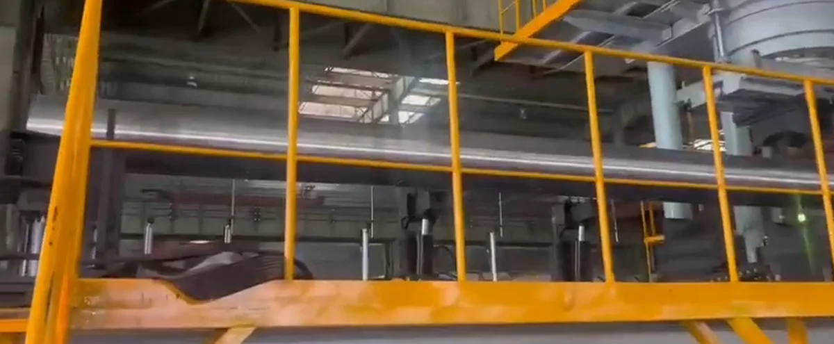
Pou pati long, sipò devyasyon ak nivo fondasyon ka enfliyanse mezi a. Komisyonè ta dwe gen ladan aliyman sipò, chèk repetibilite ak yon pwosedi zewo/referans defini anvan yo aksepte resèt pwodiksyon yo.
Mezi Bend Full-Length
Sistèm mezi a ka itilize optik lazè, kontak detèktè deplasman oswa yon lòt metòd valide pou anrejistre pwofil tiyo a sou longè li yo. Plan mezi a dwe presize rezolisyon, kalib longè, kondisyon sipò, manyen sifas epi si tiyo a mezire nan yon pozisyon revèy oswa vire pou separe pliye milti-avyon ak ovale.
Si kliyan an sèvi ak yon liy fisèl, straightedge oswa offline lazè estasyon, rezilta machin otomatik yo ta dwe konpare ak metòd sa a sou menm seri echantiyon an. Objektif la se pa sèlman repetibilite andedan machin nan, men akò ak metòd akseptasyon final la.
Koreksyon idwolik ak Pwoteksyon Seksyon
Kontwolè a chwazi yon pwen koreksyon ak span sipò ki baze sou koube a mezire. Yon soulye pou laprès kontou distribye chaj sou sifas tiyo a, pandan de oswa plis selles kreye pwen reyaksyon yo. Konjesyon serebral la dwe depase devyasyon elastik ase pou pwodui koreksyon pèmanan kontwole, men rete pi ba pase limit ki kapab dent, plati oswa fann tiyo a.
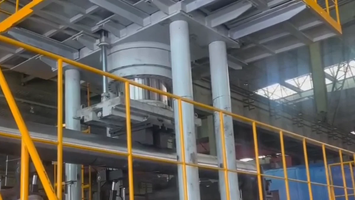
Fòs rated pa ka chwazi nan dyamèt deyò pou kont li. Sa depann de epesè miray la, klas asye ak fòs sede, sipò span, modil seksyon, koube fèk ap rantre, rezilta rezidyèl vle ak estrès lokal akseptab. Inisyal fòs/konjesyon serebral limit yo ta dwe etabli pa kalkil ak echantiyon tès reprezantan.
Remezire, Limit iterasyon ak manyen NOK
Apre koreksyon, tiyo a mezire ankò anba menm kondisyon sipò. Si rezilta a rete andeyò tolerans men repons mezire a nòmal epi resèt la nan limit valide li yo, sistèm nan ka kalkile yon lòt koreksyon. Maksimòm kou, fòs, konte koreksyon ak règ repons anòmal anpeche peze repete san kontwòl.
Yon tiyo ki pa ka rive jwenn sib la san danje ta dwe klase kòm NOK oswa voye pou revizyon jeni. Machin nan ta dwe kenbe pwofil la anvan / apre, pozisyon koreksyon, kou/fòs kote ki disponib, vèsyon resèt ak desizyon final lè trasabilite pwojè a mande sa.
Konfigirasyon selil rekòmande
| Modil | Egzijans pwopoze | Poukisa li nesesè |
|---|---|---|
| Konsèp machin | Lou-devwa idwolik twa pwen tiyo redresman laprès | Lokal, koreksyon kontwole pou gwo seksyon kre |
| Anvlòp pyès travay | OD 127-349.25 mm; miray 9.525-38.1 mm; longè 1,828.8-12,192 mm | Kouvri ranje pwojè a, sijè a konfimasyon orè gwosè |
| Rated Force / Konjesyon Serebral | Yo dwe gwosè pa kalkil ak tès echantiyon | Anpeche undersizing, twòp estrès oswa seleksyon modèl ki twonpe |
| Sistèm Mezire | Tout longè lazè/kontak pwofil mezi kòm valide | Distenge koube lokal ak jeneral epi sipòte koreksyon bouk fèmen |
| Sipò | Powered / reglabl kontou selles ak wotè defini ak espas | Kontwole pwa pwòp tèt ou ak pwoteje sifas tiyo a |
| Pozisyon | Woulo Powered, Indexing kondwi oswa ankadreman pou laprès mobil | Pote chak koube mezire nan pwen koreksyon an san danje |
| Zouti | OD-espesifik soulye pou laprès ak selles | Diminye risk pou endentasyon ak ovalite |
| Kontwòl | Resèt gwosè, pliye kat jeyografik, limit koreksyon ak lojik remezurasyon | Diminye depandans sou jijman manyèl |
| Manyen | Koòdone teknik / portik / mache gwo bout bwa / roulo ak kontwòl anti-woulo liv | Jere yon seri pati estime ki ka pwolonje nan plizyè tòn |
| Done Kalite | Profil inisyal/final, istwa koreksyon ak rezilta OK/NOK jan sa nesesè | Verifikasyon pwosesis ak trasabilite |
| Sekirite | Siveye, mouvman anklanche, pwoteksyon surcharge ak aksè san danje | Pwoteje operatè yo ozalantou yon gwo pyès travay wonn k ap deplase |
Validasyon pwojè anvan sitasyon final la
Matrice echantiyon an ta dwe kouvri pi piti ak pi gwo konbinezon OD/mi yo, tiyo ki pi kout ak pi long, viraj nòmal ak pi move ka yo, tout klas asye ki enpòtan ak nenpòt kondisyon chalè-tretman. Chak jijman ta dwe dokimante pozisyon sipò yo, oryantasyon, pwofil fèk ap rantre, pozisyon koreksyon, fòs/konjesyon serebral kote ki disponib, pwofil final la, kondisyon ovalite/sifas ak tan total sik.
Anvan sib dwat la vin tounen yon garanti machin, kliyan an dwe konfime si egzijans ki anrejistre a vle di 1 mm pou chak 1000 mm, yon lòt inite oswa yon rapò jeneral dwat. Lè sa a, metòd enspeksyon machin ak kliyan yo ta dwe korelasyon sou echantiyon yo menm.
Enfòmasyon ki nesesè pou yon pwopozisyon redresman tiyo san pwoblèm
Tanpri bay orè tiyo konplè a, klas materyèl ak fòs sede, sètifye oswa kalkile pwa, OD ak tolerans miray la, distribisyon pliye fèk ap rantre, kondisyon lokal ak jeneral dwat, estanda enspeksyon ak metòd kalib, limit ovalite, restriksyon sifas / make, kondisyon sipò, tan sik sib, volim anyèl, layout plant, koòdone teknik / roulo ak tiyo echantiyon reprezantan.
Antre sa yo pèmèt ekip solisyon an kalkile fòs ak sipò span, chwazi prensip la mezire, konsepsyon zouti kontou, defini kondisyon manyen ak sekirite, epi valide pwosesis la anvan modèl machin final la ak fòs rated yo komèt.
FAQ
Èske "1 nan 1000 mm” vle di yon pous koube pou chak 1000 mm?
Li se Limit epi yo pa ta dwe entèprete konsa san konfimasyon. Li ka gen entansyon kòm 1 mm pou chak 1000 mm kalib longè. Desen kliyan an oswa spesifikasyon dwe defini inite a, kalib longè, kondisyon sipò ak metòd enspeksyon.
Èske yon machin ka kouvri OD 127 pou 349.25 mm ak longè jiska 12.2 m?
Potansyèlman, men ranje fòs la, peze vwayaj, pozisyon sipò yo, jaden mezire, chanjman zouti ak sistèm manyen dwe kouvri orè a plen gwosè. Yon lis aktyèl OD/miray/longè konbinezon obligatwa; pwen final ranje poukont yo pa ase.
Ki jan yo anpeche tiyo plat pandan redresman laprès?
Solisyon an sèvi ak soulye pou laprès kontou ak selles, span sipò kontwole ak limit fòs/konjesyon serebral valide. Ovalite ak kondisyon sifas yo ta dwe enkli nan plan akseptasyon echantiyon tès la lè yo se kondisyon fonksyonèl.
How does the machine compensate for the pipe's own weight?
Se tiyo a mezire anba yon defini, kondisyon sipò repete. Pozisyon sipò ak wotè yo enkli nan chak resèt, and the machine result is correlated with the customer's final inspection method.
Èske tonnage machin obligatwa a deja konfime?
Non. Fòs rated dwe kalkile nan klas materyèl la, sede fòs, seksyon, sipò span ak fèk ap rantre koube, Lè sa a, valide ak echantiyon reprezantan. Paj sa a entansyonèlman pa bay yon modèl ki pa verifye oswa yon tonnaj.
Èske sistèm nan ranplase yon operatè redresman manyèl ki gen eksperyans?
Li ka estandadize mezi, seleksyon bend-kote, limit koreksyon, remezurasyon ak dosye. Operatè yo toujou mande pou ekipman pou materyèl, chèk zouti, odit enspeksyon, antretyen ak tiyo nòmal sof si selil konplè a fèt pou yon modèl anplwaye diferan.
Ki sa ki nesesè anvan sitasyon?
Pake minimòm itil se orè tiyo a, klas, pwa, koube fèk ap rantre, sib lokal/an jeneral, metòd enspeksyon, limit ovalite/sifas, sib pwodiksyon an, layout plant ak echantiyon tiyo.
Konklizyon
Gwo tiyo san pwoblèm redresman se yon metroloji konbine, koreksyon estriktirèl ak pwoblèm manyen materyèl. Rezilta final la depann sou kontwòl pwòp tèt ou-pwa, kat pliye a plen longè, distribye kontak pou laprès atravè seksyon an kre ak repete mezi anba menm kondisyon sipò.
The engineering on this page is half the picture – la manual vs automatic straightening comparison ak la automatic straightening ROI worksheet cover the commercial half of a seamless steel pipe project.
Voye orè tiyo w la, klas asye, pwofil pliye fèk ap rantre, definisyon dwat, sib pwodiksyon ak echantiyon enfòmasyon pou yon revizyon posibilite. Fòs laprès final la, zouti, sipò, sistèm mezi ak modèl machin yo ta dwe konfime atravè kalkil jeni ak esè echantiyon reprezantan.