
Nestejäähdytyssarja jakaa jäähdytysnesteen akun kautta, tietokeskus, tehoelektroniikka tai teolliset lämmönhallintajärjestelmät. Niiden pitkä ontto profiili, hitsattujen aukkojen ja tiivistysrajapintojen tulee pysyä geometrisesti vakaina, jotta kokoonpano sopii jäähdytysjärjestelmään ilman pakottamista, vuotoriski tai kohdistusongelmat.
Tämä ehdotettu ratkaisu perustuu 304 litran ruostumattomasta teräksestä valmistettuun suorakaiteen muotoiseen onttoon jakotukkiin, jonka mitat ovat noin 78 mm leveä, 45 mm korkea ja 1800 mm pitkä, kanssa a 3 mm seinään. Asiakas ilmoittaa kaksi erilaista muodonmuutosvaihetta: sisääntulevat putken päät voivat olla vääntyneet noin 20 mm, ja hitsaus saa aikaan toisen taivutusmuodonmuutoksen. Nämä ovat erilaisia vikoja, ja ne tulisi käsitellä erillisillä oikaisustrategioilla yhden yleisen puristusjakson sijaan.

Työkappale ja asiakkaan vaatimukset
Jakotukki alkaa pitkänä suorakaiteen muotoisena ontona putkena ja saa myöhemmin useita haaroja, portit tai hitsatut liittimet. Tällä hetkellä asiakas korjaa alkukäänteen manuaalisesti, ottaen noin 30 minuuttia per osa. Kierteen korjauksen jälkeen, osa on hitsattu ja voi taipua uudelleen, luoda toinen oikaisuvaatimus ennen lopullista asennusta tai vuototestausta.
Ilmoitettu tuotantomäärä on 12,000 osia kuukaudessa ja vaadittu jälkioikaisutarkkuus on 0.15 mm. Ennen kuin tästä arvosta tulee laitetakuu, piirustuksen tulee selvittää, hallitseeko se suoruutta, tasaisuus, profiili, loppuasento, portin sijainti tai muu geometrinen ominaisuus, ja millä peruspisteen pituudella se mitataan.
| Projektikohde | Asiakkaan syöttö / Status |
|---|---|
| Työkappale | Nestejäähdytyssarja / jakelusarja |
| Materiaali | 304L ruostumatonta terästä |
| osio | Suorakaiteen muotoinen ontto profiili, suunnilleen 78 × 45 mm |
| Seinän paksuus | 3 mm |
| Pituus | suunnilleen 1800 mm |
| Alkuperäinen vika | Putken pään kierre raportoitu noin klo 20 mm |
| Toinen vika | Taivutus hitsauksen jälkeen |
| Nykyinen menetelmä | Manuaalinen kierteen korjaus, suunnilleen 30 min/osa |
| Tuotantomäärä | 12,000 osat/kk |
| Vaadittu tarkkuus | 0.15 mm; ominaisuus ja perusarvo vahvistettava |
| Ratkaisuehdotus | Kierteen korjauslaitteet sekä taivutusoikaisukone |
Kierros ja taivutus on mitattava erikseen
Twist tarkoittaa, että yksi poikkileikkaus on kiertynyt suhteessa toiseen profiilin pituudella. Taivutus tarkoittaa, että pituussuuntainen keskiviiva tai vertailupinta poikkeaa vaaditusta linjasta. Jakotukki voi olla suora sivulta katsottuna, mutta siinä voi silti olla pyörivät päät, tai sillä voi olla oikea päätesuunta hitsauksen jälkeen taipuessa.
Pelkän pystysuuntaisen siirtosondin käyttäminen ei voi täysin kuvata vääntövirhettä. Kierreasema tarvitsee suorakulmaisen profiilin tai päätypisteiden kulma- tai monipinnamittauksen. Taivutus-oikaisuasema tarvitsee lineaarimittauksia sovituilla referenssipintoja tai keskilinjaa pitkin. Portin ja laipan sijainti saattaa vaatia lisämittareita, jos ne ovat toiminnallisia hyväksymisominaisuuksia.
| Vika | Tyypillinen mittaus | Pakollinen korjaus |
|---|---|---|
| Lopeta kierre / vääntö | Päätypoikkileikkausten kulmavertailu, monipinta-anturit, laser- tai valaisinmittari | Hallittu vastamomentti tai vääntöoikaisu |
| Pystysuora keula | Siirtymän mittaus ylä-/alapisteen mukaan | Pystypuristimen korjaus |
| Vaakasuora jousi | Sivumitta referenssipintaa tai keskiviivaa pitkin | Vaakasuuntainen korjaus tai uudelleensuuntaus |
| Paikallinen hitsausvääristymä | Mittaus lähellä hitsattuja aukkoja tai lämpövaikutusalueita | Paikallinen pistekorjaus jännitysrajoilla |
| Portti / sovitusvirhe | Teline, visio, CMM tai erillinen toimintamittari | Erillinen hyväksyntä tai paikallinen korjaus, jos se on vahvistettu |
The 0.15 mm:n vaatimusta ei voida määrittää kaikille näille ominaisuuksille ilman näyttöä. Jokaisella ohjatulla ominaisuudella tulee olla oma peruspisteensä, mittauspaikka ja OK/NOK-sääntö.
Miksi nestejäähdytysjakoputkia on vaikea oikaista
The 3 mm ontto seinä aiheuttaa puristumisvaaran, painauma tai paikallinen lommahdus keskitetyn tuen tai puristuskontaktin alla. Suorakaiteen muotoisella poikkileikkauksella on erilainen jäykkyys sen pää- ja sivuakselien suhteen, joten sama painallus tuottaa erilaisia vasteita suunnasta riippuen. The section-preservation logic for smaller hollow parts is covered in ohutseinäisten putken oikaisu.
Hitsaukset tekevät vasteesta vieläkin epäyhtenäisemmän. Lämmönsyöttö ja hitsausjärjestys voivat vetää jakotukia kohti hitsattua puolta, kun taas monet portit luovat paikallisia jäykkyysmuutoksia. Portin painaminen, hitsaushelmi, tiivistepinta tai ohut tukematon seinä voi vahingoittaa toiminnallista ominaisuutta. Prosessissa on siksi käytettävä muotoiltua tukea ja puristustyökaluja, jotka on sijoitettu kriittisten ominaisuuksien väliin tai ympärille.
| Haaste | Riski | Tekninen ohjaus |
|---|---|---|
| 1800 mm pitkä profiili | Omapaino ja epävakaa mittaus | Hajautetut tuet ja datum-pohjainen täyspitkä mittaus |
| 3 mm ontto seinä | Murskaus tai pysyvä painauma | Leveä muotoiltu työkalu, sisäistä tukea tarvittaessa, voiman/iskun rajat |
| Suorakaiteen muotoinen osa | Eri jäykkyys suunnan mukaan | Erillinen pystysuora, vaaka- ja vääntöreseptit |
| Noin 20 mm pään kierre | Ei voida poistaa luotettavasti yksinkertaisella pystypuristamalla | Erillinen vääntöasema ja kulmapalautus |
| Useita hitsattuja portteja | Paikallinen jäykkyys ja lämpövääristymä vaihtelevat pituuden mukaan | Mallikohtaiset puristusvyöhykkeet ja paikallinen mittaus |
| 12,000 osat/kk | Manuaalinen 30 minuutin prosessi ei tue vaadittua tulosta | Automaattinen käsittely, rinnakkaiset toiminnot ja taktiajan validointi |
Suositeltu kaksivaiheinen oikaisukonsepti
Suositeltava konsepti erottaa esihitsauksen kierteen korjauksen hitsauksen jälkeisestä taivutuksen korjauksesta. Ensimmäinen asema vastaanottaa suorakaiteen muotoisen putken tai esikokoonpanon, paikantaa molemmat päät ja mittaa suhteellisen kulmavirheen. Ohjattu pyörivä toimilaite tai vastakkaiset puristimet käyttävät vastamomenttia validoiduin askelin, sen jälkeen uudelleenmittaus.
Hitsauksen jälkeen, jakotukki menee pitkäpetipisteen oikaisuasemaan. Useat tuet muodostavat peruspisteen, anturit kartoittavat mutkan pituussuunnassa, ja liikkuva tai indeksoitu puristin käyttää ohjattua korjausta hyväksytyissä paikoissa. Projektivideolla näkyy tämä pitkä ja monimutkainen puristusoikaisukonsepti; se ei näytä tai todista erillistä esihitsauksen vääntökorjausasemaa.
Vaihe 1: Esihitsauksen kierteen korjaus
Vaihe 1: Tunnista profiili ja määritä lopetuspäivämäärät
Valaisin paikantaa suorakaiteen muotoisen putken sovittujen referenssipintojen tai päätyominaisuuksien avulla. Kiinnittimien on jaettava kosketus koko 3 mm seinään ilman kolhuja. Jos osa sisältää jo herkkiä liitoksia, nämä alueet jäävät kiinnitysvyöhykkeiden ulkopuolelle.
Vaihe 2: Mittaa alkuvääntö
Järjestelmä vertailee molempien päiden tai useiden poikkileikkausten kulmasuuntausta. Raportoitu "20 mm:n kierre" tulee muuntaa määritellyksi geometriseksi mittaukseksi - kuten päätykulman siirtymä tunnetulla mittasäteellä tai kulma-asteilla - jotta ohjausjärjestelmä ja asiakkaan tarkastus käyttävät samaa määritelmää.
Vaihe 3: Käytä ohjattua vastamomenttia
Toista päätä pidetään paikallaan, kun taas toista käännetään vastakkaiseen suuntaan käyttämällä säädeltyä vääntömomenttia tai kulmasiirtymää. Koska 304L ruostumaton teräs joustaa takaisin, asema tarvitsee validoidun over-twist-strategian. Suurin vääntömomentti, kulma- ja korjaussyklit suojaavat onttoa osaa ja mahdollisia hitsattuja saumoja.
Vaihe 4: Mittaa uudelleen ja hyväksy esihitsausosa
Osa mitataan uudelleen jokaisen korjauksen jälkeen. Vain profiilit, jotka ovat sovitun esihitsauksen vääntörajan sisällä, jatkavat hitsaukseen. Saapuvan ja korjatun kierteen tallentaminen voi myös paljastaa putken syöttöongelmia, varastointiin tai alkupään muovaukseen.
Vaihe 2: Hitsauksen jälkeinen taivutuksen oikaisu
Vaihe 1: Kuormaa ja tue hitsattu jakotukki
Valmis tai puolivalmis jakotukki asetetaan hajautetuille säädettäville tuille. Valaisimen on otettava huomioon pitkä runko, useita portteja ja erilaisia päätyrakenteita jättäen samalla vapaan pääsyn antureille ja puristuspäälle.
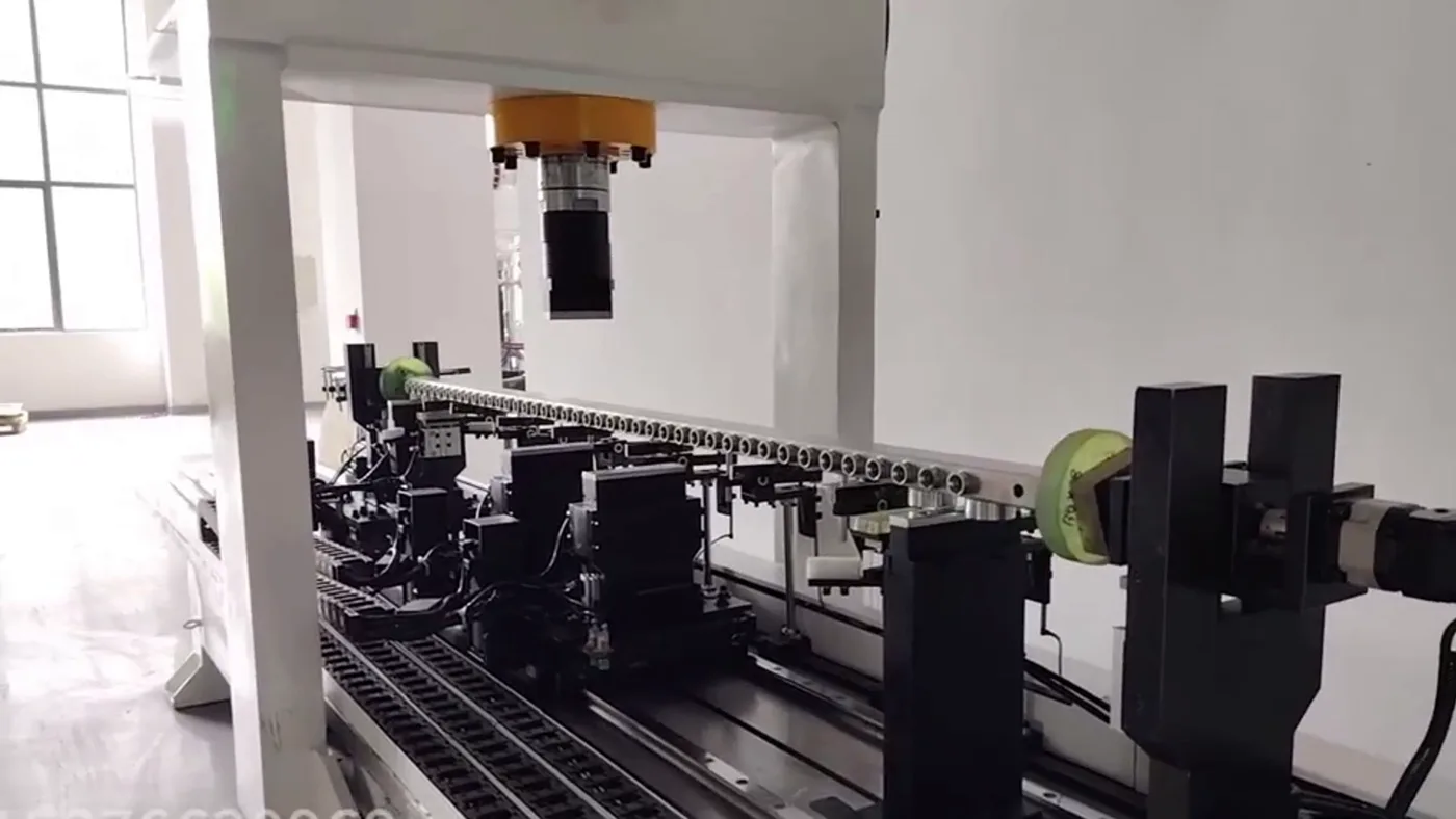
Tukipisteiden tulee koskettaa hyväksyttyjä leveitä pintoja. Portit, hitsaushelmiä, tiivistepinnat ja ohuet tukemattomat seinät määritellään suojatuiksi vyöhykkeiksi. Contact-zone validation follows the same pintasuojaustyökalut rules.
Vaihe 2: Kartoita hitsin aiheuttama muodonmuutos
Yhteysanturit, laseranturit tai niiden yhdistelmä mittaavat relevantin vertailupinnan useissa kohdissa. Säädin erottaa kokonaiskaaren paikallisesta muodonmuutoksesta hitsien lähellä. Jos sekä pysty- että vaakataivutusta ohjataan, järjestelmä tarvitsee mittauksia molempiin suuntiin tai validoidun osien uudelleensuuntaussekvenssin.
Vaihe 3: Laske paino- ja tukiasemat
Ohjaus tunnistaa taivutushuipun ja valitsee turvallisen korjauspisteen kriittisten porttien välillä. Paikallinen osan jäykkyys, etäisyys lähimpään hitsauskohtaan ja tukijänne vaikuttavat alkuiskuon. Strategiassa tulee välttää yksinkertaisesti painamista suurimmalla mitatulla poikkeamalla, kun kyseinen sijainti on heikko tai toimiva alue.
Vaihe 4: Käytä ohjattua painonkorjausta
Puristin käyttää rajoitettua ylitaivutusiskua takaisinjouston kompensoimiseksi. Leveä muotoiltu työkalu jakaa kuorman suorakaiteen muotoiseen putkeen. Missä seinän romahtamisen riski on suuri, sisäiset karat, Paikallisia täyteaineita tai erikoistunutta ulkopuolista tukea voidaan tarvita teknisen arvioinnin jälkeen.

Voiman ja siirtymän rajat tulee kehittää edustavista hitsatuista näytteistä. Äkillinen muutos voima-siirtymävasteessa voi olla merkki väärästä tuesta, eri osamalli tai paikallinen romahdus ja sen pitäisi laukaista hälytys.
Vaihe 5: Suljetun silmukan uudelleenmittaus
Korjauksen jälkeen, jakotukki mitataan samasta peruspisteestä. Lisäkorjaus on sallittu vain validoidun syklin ja iskurajojen sisällä. Jos osa ei pääse kohteeseen vaarantamatta porttia, hitsaus- tai seinävaurioita, se lähetetään NOK:iin tai manuaaliseen suunnittelukatsaukseen.
Vaihe 6: Lopputarkastus ja siirto
Lopullinen hyväksyntä voi sisältää suoruuden/tasaisuuden, loppusuunta, portin sijainti, pinnan kunto ja vuototestit. Suoristuslaitteen ei pitäisi väittää varmistavansa vuotojen eheyttä, ellei integroitua vuodontestausasemaa todella ole mukana.
Kapasiteetti Tarkista 12,000 Osat kuukaudessa
Tuotantomäärä on muutettava taktiajaksi todellisia työpäiviä käyttäen, vuoroja, käytettävissä olevat työajat ja laitteiden käyttöaste. Esimerkiksi, 12,000 osat kuukaudessa eivät voi itse määritellä tarvittavaa sykliä ennen kuin tiedetään tuotantotuntien määrä ja se, tarvitaanko jokaiselle osalle molempia korjausvaiheita.
Nykyinen manuaalinen vääntökorjaus noin 30 minuuttia per osa tarjoaa lähtötilanteen, ei automaattisen koneen tulos. Täydellisen kapasiteettimallin tulisi sisältää lastaus, mittaus, korjaus, uudelleenmittaus, purkaminen, vaihto, työkalun tarkastus, suunniteltu seisokkiaika ja lisäjaksoja tarvitsevien osien prosenttiosuus.
| Kapasiteetin syöttö | Vaadittu arvo |
|---|---|
| Kuukauden määrä | 12,000 osat |
| Työpäivät/kuukausi | Asiakas vahvistaa |
| Vuorot/päivä ja tunnit/vuorot | Asiakas vahvistaa |
| Kohde OEE / käyttö | Asiakas vahvistaa |
| Prosenttiosuus, joka vaatii esihitsauksen kierteen korjauksen | Mitattava |
| Hitsauksen jälkeisen taivutuksen korjauksen vaativa prosenttiosuus | Mitattava |
| Keskimäärin / enimmäiskorjausjaksot | Näytetestin tulos vaaditaan |
| Tarvittava puskuri hitsauksen ja oikaisun välillä | Linjaasettelupäätös |
Ehdotettu solukokoonpano
| Moduuli | Ehdotettu kokoonpano |
|---|---|
| Pre-Weld Station | Profiilin kiinnitys, kulma/vääntömittaus ja ohjattu vastakääntö |
| Post-Weld Station | Pitkän sängyn puristussuoristus, jossa säädettävät hajautetut tuet |
| Mittausjärjestelmä | Kulma-/päätepistemittaus sekä monipisteinen lineaarinen siirtymän tunnistus |
| Työkalu | Laaja muotoinen kontakti 78 × 45 × 3 mm ontto osa |
| Painamalla | Liikkuva tai indeksoitu puristuspää, jossa voima-/siirtymärajoitukset |
| Käsittely | Manuaalinen apu, portaali tai robotti osan painon ja tahdin mukaan |
| Säätimet | Erilliset esi- ja jälkihitsausreseptit, suljetun silmukan korjaus ja OK/NOK-logiikka |
| Data | Saapuva/lopullinen kierre ja mutka, korjausmäärä, resepti ja osatunnus tarpeen mukaan |
| Turvallisuus | Lukittu vartiointi, ylikuormitussuoja ja epänormaalin romahtamisen havaitsemisstrategia |
Projektin validointisuunnitelma
Edustavien näytteiden tulee sisältää normaali ja suurin saapuva kierre, eri hitsauserät ja suurin odotettu hitsin jälkeinen muodonmuutos. Testissä on varmistettava, onko 3 mm profiilia voidaan korjata ilman sisennystä, porttivaurio, hitsaushalkeamia tai ei-hyväksyttävää jäännösjännitystä.
Hyväksymisraportissa tulee selkeästi mainita asiakkaan vaatimukset, näytetestien tulokset ja myöhemmin tuotantotulokset. Siinä olisi myös määriteltävä, onko 0.15 mm on saavutettavissa ja merkityksellinen kokonaisuuden kannalta 1800 mm jakotukki, paikallinen peruspistealue, tiivistävä pinta, portin sijainti tai muu piirustusominaisuus.
Nestejäähdytyssarjaehdotusta varten tarvittavat tiedot
Ole hyvä ja toimita täydellinen piirustus ja GD&T, 3D malli, materiaalitodistus, hitsausjärjestys, osa painoa, saapuvan kierteen määrittely ja jakelu, hitsin jälkeinen muodonmuutoskartta, lopullinen toleranssi ja datum, suojattuja pintoja, sallitut puristus-/tuki-/puristusalueet, vaaditut vuoto- ja pintakriteerit, työkalenteri, tavoitekorko, linja-asettelu ja edustavat esi- ja jälkihitsausnäytteet.
Nämä syötteet määrittävät, tarvitseeko projekti kaksi itsenäistä konetta, yhdistetty solu, useita korjausakseleita, sisäinen putken tuki, automaattinen käsittely tai alavirtamittari.
FAQ
Pystyykö yksi kone korjaamaan sekä vääntymisen että taipumisen?
On mahdollista integroida useita akseleita yhteen mukautettuun soluun, mutta vääntyminen ja taivutus vaativat silti erilaisia mittauksia ja korjaustoimenpiteitä. Erilliset asemat ovat usein selkeämpiä ja helpompia validoida suuren volyymin linjalle.
Miksi pelkkä pystypuristin ei riitä raportoidulle? 20 mm kierre?
Pystypuristus korjaa ensisijaisesti taivutuksen. Vääntö vaatii profiilin päiden hallittua suhteellista pyörimistä tai muuta validoitua vääntömekanismia, jossa on kulmapalaute.
Kuinka on 3 mm ruostumattomasta teräksestä valmistettu seinä suojattu?
Kiinnitys ja puristin käyttävät laajaa muotoiltua kosketusta hyväksytyillä pinnoilla, konservatiivisilla voima-/iskurajoilla. Sisäistä tukea voidaan tarvita, jos paikallinen romahtamisriski on suuri.
Voiko linja saavuttaa 0.15 mm tarkkuudella?
Arvo tarvitsee ensin piirustuksen määritelmän ja peruspisteen. Saavutettavuus riippuu sitten täydellisestä geometriasta, hitsin jakelu, aineellinen vastaus, mittausmenetelmä ja näytetestitulokset.
Kestääkö tämä prosessi 12,000 jakoputket kuukaudessa?
Kuukauden volyymi on muutettava taktiajaksi työpäiviä käyttäen, vuoroja, OEE ja kunkin korjausvaiheen vaativien osien prosenttiosuus. Kapasiteetti vahvistetaan vasta, kun näytejaksotiedot ovat saatavilla.
Näyttääkö video täydellisen kaksivaiheisen ratkaisun?
Ei. Siinä näkyy pitkän jakoputken puristusoikaisuasema. Ehdotetussa ratkaisussa kuvattu erillinen esihitsauksen kierteen korjauslaitteisto ei ole todistettavissa tällä videolla.
Johtopäätös
Nestejäähdytyssarjat vaativat enemmän kuin yleisen oikaisupuristimen. Tulevassa suorakaiteen muotoisessa putkessa voi olla vääntövirhe, hitsaus luo toisen taivutusmuodonmuutoksen, ja ohut 304L ontto osa on korjattava ilman puristusaukkoja, hitsit tai tiivistysliitännät.
To turn this liquid-cooling manifold guidance into a purchase decision, start with the suoristimen valinnan esittely and pressure-test the numbers with the budjettikuva oikaisukoneeseen.
Lähetä jakotukin piirustus, kierre määritelmä, hitsausjärjestys, hitsin jälkeiset muodonmuutostiedot, kohdepiste, kuukausittainen tuotantokalenteri ja edustavat näytteet. Voimme sitten suunnitella ja valmistaa validoidun esihitsauksen kierre- ja hitsauksen jälkeisen taivutusoikaisuratkaisun todellisen työkappaleen ja tahdin vaatimuksen mukaan..