
Los componentes del taladro médico de pequeño diámetro son difíciles de enderezar porque la fuerza de medición, espaciado de soporte, El error de sujeción y el incremento de corrección pueden ser significativos en relación con la rigidez de la pieza de trabajo.. Una pieza puede aparecer recta en un dispositivo y mostrar una desviación diferente cuando se hace referencia a ella desde su vástago funcional o referencia de ensamblaje final..
Esta solución se basa en un proyecto fuente publicado que informa un Ø2 mm × 70 pieza de trabajo de mm y un 0.05 requisito de rectitud mm. Esos números se tratan como entradas de clientes., resultados de producción no tan probados. Una garantía requiere el dibujo controlado., dato, método de calibre, Muestras representativas y registros de antes y después..
Entradas reportadas del proyecto y estado de la evidencia
| Artículo | Entrada publicada | Estado de la evidencia |
|---|---|---|
| Pieza de trabajo | Pequeño componente de taladro médico | Fotos reales de piezas y equipos disponibles. |
| Diámetro | 2.0 milímetros | Reportado en el artículo fuente.; dibujo no adjunto |
| Longitud | 70 milímetros | Reportado en el artículo fuente.; dibujo no adjunto |
| Objetivo | 0.05 mm rectitud | Requisito del cliente según lo informado; informe de resultados no disponible |
| Material / dureza | No declarado | Debe ser confirmado |
| Dato funcional | No declarado | Debe definirse a partir del dibujo y el uso. |
| Etapa del proceso | No declarado | Dientes, tratamiento térmico, Se debe confirmar el estado del recubrimiento y del pulido final. |
| Resultado de producción | Reclamado como logrado | No se utiliza como un hecho sin registros de medición y capacidad. |

Por qué el diámetro pequeño cambia la medida
Para una parte delgada, la sonda puede desviar la pieza de trabajo, the supports can impose a shape and the part's own orientation can change the reading. La solución debe definir más que la resolución del sensor.
Un artículo separado sobre taladros quirúrgicos señala que normalmente es necesario enderezar la pieza en bruto antes de esmerilarla., con agotamiento mantenido dentro de aproximadamente 0.1 mm en esa etapa. Ese valor describe un requisito común de la etapa del proceso en lugar de una tolerancia universal.; La etapa y la tolerancia deben ser confirmadas en cada dibujo..
Dato funcional
La convención de referencia del vástago de sujeción sigue la guía de piezas de trabajo de MAE para taladros.; la cita completa y sus implicaciones en la elección de datos se encuentran en la página página de enderezamiento de taladro médico dentado.
Fuerza de la sonda y geometría de contacto.
Fuerza de la sonda, La forma del lápiz óptico y la ubicación de contacto deben ser lo suficientemente bajas y estables como para no doblar o marcar el componente.. El sistema de medición debe demostrar repetibilidad en una pieza maestra o representativa antes de usarse para controlar la corrección..
Espaciado de soporte
Los soportes deben estabilizar la pieza de trabajo sin forzarla a enderezarse.. Sus posiciones, Los radios y el material de contacto pasan a formar parte de la receta controlada..
Rectitud versus descentramiento
el original 0.05 La declaración mm llama a la rectitud característica., pero una máquina rotativa puede en realidad informar descentramiento radial o TIR. El sorteo debe resolver esta diferencia antes de que se haga una promesa numérica..
Manipulación automática de piezas pequeñas
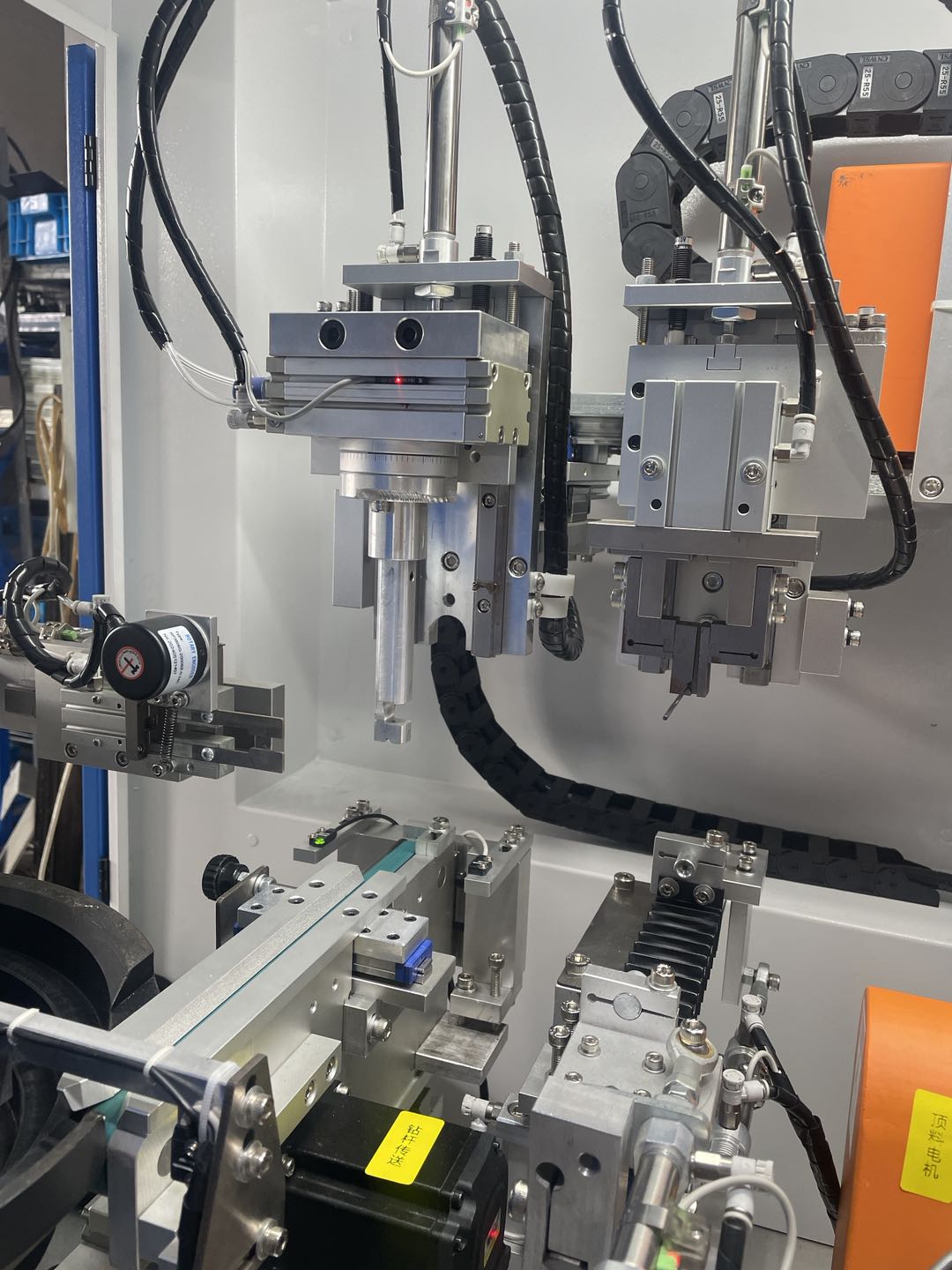
Las fotografías originales muestran una máquina compacta con alimentador de cuenco., mecanismo de transferencia y herramientas de medición/corrección dedicadas. Estas imágenes confirman que la separación y carga automatizadas se desarrollaron para una pequeña familia de componentes.; no acreditan una tasa de producción o un período de producción desatendida.

El diseño de manipulación debe verificarse para:
- Orientación de piezas y reconocimiento de características finales.;
- riesgo de enredo o superposición;
- contacto con superficies acabadas o críticas;
- transferir la repetibilidad al punto de referencia de medición;
- Prevención de partes mixtas y control de recetas.;
- Rechazo de contención y limpieza de líneas..
Proceso de circuito cerrado recomendado
1. Identificar y orientar
El alimentador separa las piezas y presenta el final y la orientación correctos.. Los controles de presencia y asiento evitan una ciclo con una pieza faltante o duplicada..
2. Establecer el dato funcional
La pieza de trabajo está ubicada en su vástago aprobado., centros o referencias definidas por el dibujo. La fuerza de sujeción se limita para evitar introducir una falsa curvatura..
3. Mida la condición entrante
La pieza gira o se indexa mientras las sondas de baja fuerza leen las posiciones aprobadas.. El sistema registra la condición inicial y confirma que la señal está dentro del rango validado..
4. Aplicar microcorrección
La herramienta de prensa aplica un control, desplazamiento limitado en una zona lisa aprobada. Se prefieren pequeñas correcciones y límites de fuerza/carrera a un gran movimiento único..
5. Remedir
Se utiliza el mismo método de referencia y sonda inmediatamente después de la corrección.. Si el resultado queda fuera del objetivo, se permite otra corrección solo dentro del límite de iteración validada.
6. Disposición y registro
La parte es aceptada., rechazado o retenido para revisión de acuerdo con la regla específica del dibujo. Los datos requeridos se pueden almacenar o exportar cuando se incluyen en el alcance del proyecto aprobado..
Vídeo relacionado con el enderezamiento de taladros médicos
El siguiente vídeo del canal Máquina enderezadora se titula “Cómo enderezar una broca con una máquina enderezadora” y describe una máquina de brocas médica personalizada. Demuestra una celda automática de enderezamiento de taladro médico.. The video description's customer location and labor-saving statement are not used as verified project results.
Validando el 0.05 mm Objetivo
El reportado 0.05 El requisito de mm es técnicamente incompleto hasta que se definan la característica y el dato..
| Artículo de validación | Definición requerida |
|---|---|
| Característica | Rectitud, descentramiento radial, TIR o coaxialidad |
| Dato | Mango funcional, centros, diarios o calibre dedicado |
| Posiciones de medición | Ubicaciones y superficies axiales exactas |
| Indicador | Resolución, fuerza de la sonda, estado del dispositivo y de calibración |
| Correlación | Acuerdo entre la máquina y la inspección final del cliente. |
| ventana entrante | Doblez máxima y forma permitida antes de enderezar |
| Aceptación superficial | Marcas permitidas, rebabas y zonas críticas |
| Evidencia de capacidad | Tamaño de muestra y criterio estadístico requerido por el cliente |
La declaración pública correcta es: el proyecto fuente informó un 0.05 objetivo mm; El logro permanece sin verificar hasta que se proporcionen los registros asociados..
Interfaz del sistema de calidad médica
A este proceso se aplica el Reglamento del Sistema de Gestión de Calidad de la FDA a través del sistema de calidad legal del fabricante.; toda la discusión regulatoria vive en el página de enderezamiento de taladro médico dentado. El papel de la célula enderezadora está limitado: puede soportar registros controlados – ID de pieza/lote, revisión de dibujos y recetas, resultados de la medición, recuento y disposición de corrección – dentro de un proceso validado propiedad del fabricante. La máquina no certifica de forma independiente el cumplimiento de la FDA o ISO..
Ejemplo de plan de prueba y aceptación
- Suministrar muestras representativas en múltiples condiciones de curvatura entrante.;
- identificar material, dureza, Tratamiento térmico y estado superficial.;
- congelar datos, apoya, Zonas de contacto de corrección y fuerza de la sonda.;
- ejecutar repetir la medición antes de la corrección para cuantificar la variación de la medición;
- registrar cada resultado antes/después y cada intento rechazado;
- compare machine readings with the customer's final gauge;
- inspeccionar las superficies funcionales en busca de marcas definidas o daños;
- probar la orientación automática, controles de transferencia y de partes mixtas;
- aprobar solo la pieza de trabajo demostrada y la ventana de condición entrante.
Páginas y equipos relacionados
Ver el Soluciones de enderezamiento de dispositivos médicos, Aplicación de enderezamiento de brocas médicas y máquina enderezadora de taladro quirúrgico ortopédico ZD300. Las cifras del catálogo son información de selección preliminar y deben conciliarse con los resultados de la muestra y la cotización final..
Lo que esta solución no promete sin pruebas
- que la pieza mostrada es un dispositivo médico terminado o aprobado;
- que cada Ø2 × 70 La pieza en mm utiliza el mismo material o dato.;
- estable 0.05 producción en mm sin un estudio de capacidad y calibre definido;
- tiempo de un ciclo, mejora del rendimiento o ahorro de mano de obra;
- Cero marcas o daños sin una especificación de inspección.;
- que un alimentador/juego de herramientas cubra múltiples familias de piezas;
- FDA o ISO automático 13485 cumplimiento.
Información para enviar para una propuesta
Para taladros de pequeño diámetro, El paquete de propuesta debe poner en primer plano los elementos pequeños.: Fuerza de la sonda versus deflexión en secciones delgadas., límites de deformación de sujeción, y estabilidad alimentaria al ritmo planificado, junto al dibujo, definición de muestras y datos. El contenido general del paquete se enumera en la página de enderezamiento de taladro médico dentado.
Contacto StraighteningTech Organizar un estudio de viabilidad y correlación de mediciones basado en muestras..
Preguntas frecuentes
Es 0.05 mm de rectitud garantizada para esta pieza de trabajo?
No solo del artículo publicado.. Es un requisito reportado.. Una garantía requiere el dibujo., dato, medir la correlación y los resultados de muestras representativas.
¿Por qué es importante la fuerza de la sonda para un 2 mm parte?
Debido a que la sonda y el accesorio pueden desviar un componente delgado y cambiar la lectura aparente. La fuerza de la sonda y la disposición de soporte deben validarse como parte del método de medición..
¿Puede el alimentador manejar varios tamaños??
Potencialmente con piezas de cambio., pero orientación, superposición, El contacto y la transferencia de la superficie deben probarse para cada familia.. Una receta de software por sí sola no es suficiente.
¿Puede esta página utilizar el mismo proceso que un taladro médico dentado??
La lógica de circuito cerrado es similar, pero los riesgos de medición y herramientas difieren. Una pieza dentada/no redonda necesita una medición con reconocimiento de perfil, mientras que una pequeña parte plana o escalonada está dominada por la medición y manipulación de baja fuerza.
¿La máquina hace que el proceso sea compatible con la FDA??
No. Puede soportar un control, proceso validado y registros requeridos. El fabricante legal posee la aplicabilidad regulatoria y el cumplimiento del sistema de calidad..
Límite de referencia técnica
Fuentes externas – la guía de perforación MAE y el Reglamento del Sistema de Gestión de Calidad de la FDA – están listados en el página de enderezamiento de taladro médico dentado. Establecen principios de ingeniería y sistemas de calidad.; no prueban lo denunciado 0.05 mm resultado del proyecto.
La elección de una máquina para trabajos de perforación médica de pequeño diámetro implica algo más que un tonelaje: el guía de selección de máquinas para ejes, tubos y perfiles y el desglose de precios para máquinas enderezadoras cubrir las decisiones que la mayoría de los compradores toman mal.