
Οι χαλύβδινοι άξονες και τα κυλινδρικά εξαρτήματα τύπου ράβδου μπορούν να αναπτύξουν πλώρη και ακτινική διαρροή μετά από θερμική επεξεργασία, στροφή, άλεσμα, αποθήκευση ή χειρισμός. Όταν το τεμάχιο εργασίας περιέχει πολλές διαμέτρους, το πρόβλημα της διόρθωσης δεν είναι απλώς «κάντε τη μπάρα ευθεία»: το μηχάνημα πρέπει να περιστρέψει το εξάρτημα σε ένα συμφωνημένο δεδομένο, μετρήστε μόνο εγκεκριμένες διαμέτρους, επιλέξτε ένα ή περισσότερα ασφαλή σημεία διόρθωσης και προστατέψτε το καθορισμένο φινίρισμα επιφάνειας.
Αυτή η προτεινόμενη λύση βασίζεται σε 25 χάλυβα ή ισοδύναμο υλικό, σκληρότητα HB 241–302, μήκη από 183 να 720 mm και διαμέτρους μέτρησης από 14 να 23.5 mm. Ο πελάτης καταγράφει μια μέγιστη εισερχόμενη εξάντληση από 0.5 mm και στόχος εξόδου εξωτερικής διαμέτρου 0.2 mm, με 1–5 σημεία ευθυγράμμισης. Αυτές είναι εισροές έργου και πρέπει να συσχετίζονται με το σχέδιο, δεδομένο, θέσεις μέτρησης και αντιπροσωπευτικές δειγματοληπτικές δοκιμές πριν γίνουν εγγυήσεις αποδοχής του μηχανήματος. The underlying closed-loop principle is explained in πώς λειτουργεί το αυτόματο ίσιωμα άξονα.
Ατσάλινο Άξονας / Απαιτήσεις μπαρ και έργου
Τα δεδομένα πελατών διακρίνουν τις διαμέτρους μέτρησης και μη, που υποδηλώνει πρόβλημα επιθεώρησης περιστρεφόμενου άξονα/διαρροής αντί για απλό έλεγχο πλήρους μήκους ευθείας. Το τελικό σχέδιο πρέπει να προσδιορίζει το λειτουργικό δεδομένο, τις ακριβείς διαμέτρους μέτρησης και τα χαρακτηριστικά που μπορούν να χρησιμοποιηθούν για στήριξη, περιστροφή και πίεση.
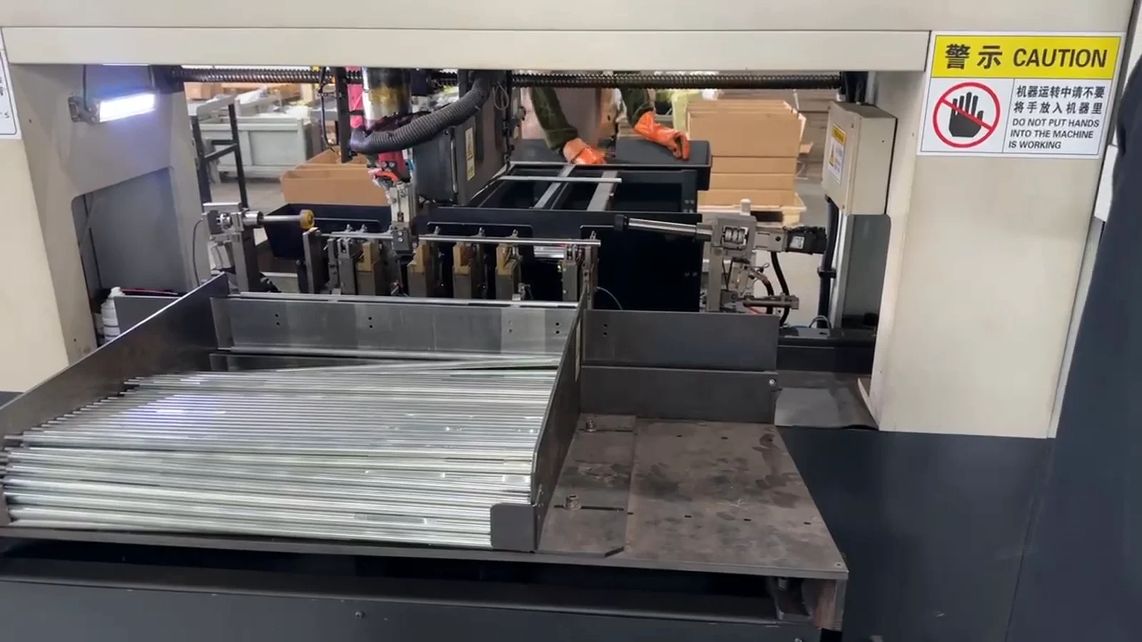
Το βίντεο του δημόσιου έργου τιτλοφορείται ως μηχάνημα ισιώματος σωλήνων και δείχνει μια παρτίδα κυλινδρικού υλικού που εισέρχεται σε έναν σταθμό μέτρησης/πρεσών πολλών σημείων. Γιατί κανένα τελικό πρόσωπο δεν φαίνεται καθαρά, το υλικό δεν αποδεικνύει εάν τα μέρη είναι συμπαγείς ράβδοι ή κοίλοι σωλήνες, ούτε αποδεικνύει ότι είναι τα δηλωμένα 25 τεμάχια κατεργασίας χάλυβα. Επομένως, αυτό το άρθρο χρησιμοποιεί τις προδιαγραφές του πελάτη για να ορίσει μια πρόταση χαλύβδινου άξονα/ράβδου και χρησιμοποιεί το βίντεο μόνο ως απόδειξη της γενικής ιδέας του αυτοματισμού κυλινδρικού αποθέματος.
| Στοιχείο έργου | Εισαγωγή πελατών / Κατάσταση |
|---|---|
| τεμάχιο εργασίας | Χάλυβας άξονας / κυλινδρικό τμήμα τύπου ράβδου; η τελική αίτηση πρέπει να επιβεβαιωθεί |
| Υλικό | 25 χάλυβα ή ισοδύναμο; απαιτείται ακριβές πρότυπο και πιστοποιητικό |
| Επιφανειακή τραχύτητα | Ra 1.25 μm |
| Σκληρότητα | HB 241–302 |
| Μέγιστο εισερχόμενο Runout | 0.5 mm εισόδου πελάτη |
| Στόχος OD Runout | 0.2 mm απαίτηση πελάτη; δεδοµένο και µέθοδος µέτρησης που πρέπει να επιβεβαιωθούν |
| Διάμετρος μέτρησης | 14.0–23,5 χλστ |
| Άλλη διάμετρος | 14.0–28,5 χλστ |
| Μήκος | 183– 720 χλστ |
| Ισιωτικές θέσεις | 1– 5 στοιχεία πελατών; απαιτείται ορισμός σημείου μέτρησης/διόρθωσης |
| Προτεινόμενη Μέθοδος | Αυτόματη περιστρεφόμενη μέτρηση με σημείο πίεσης-ίσιωμα και πλήρη επαναμέτρηση |
Το Radial Runout ορίζεται από το σημείο αναφοράς
Η ακτινική διαρροή είναι η διαφορά μεταξύ των μέγιστων και ελάχιστων ενδείξεων ανιχνευτή ενώ το τεμάχιο εργασίας περιστρέφεται γύρω από έναν καθορισμένο άξονα. Εάν ο άξονας στηρίζεται σε κέντρα, δύο περιοδικά, κυλίνδρους ή άλλο ζεύγος διαμέτρων, κάθε ρύθμιση μπορεί να παράγει διαφορετικό αποτέλεσμα. The customer's 0.2 Ο στόχος mm πρέπει επομένως να συνδεθεί με το ίδιο σημείο αναφοράς που χρησιμοποιήθηκε στην τελική επιθεώρηση.
Η ευθύτητα και η εξάντληση σχετίζονται αλλά δεν είναι εναλλάξιμα. Μια ευθεία επιφάνεια μπορεί ακόμα να εμφανίζει εξάντληση εάν το δεδομένο είναι έκκεντρο, και μια φαινομενικά αποδεκτή διαρροή σε μια διάμετρο μπορεί να κρύβει μια κάμψη σε μια άλλη αξονική θέση. Η συνταγή του μηχανήματος πρέπει να προσδιορίζει κάθε απαιτούμενο σημείο μέτρησης, η διάμετρός του, επιτρεπόμενο τόξο επαφής ανιχνευτή και όριο αποδοχής.
| Στοιχείο ελέγχου | Απαιτούμενος ορισμός |
|---|---|
| Δεδομένο | Κέντρα, επιλεγμένα περιοδικά ή καθορισμένες διαμέτρους αναφοράς |
| Μέτρηση διαμέτρων | Ακριβείς θέσεις εντός της αναφερόμενης περιοχής 14–23,5 mm |
| Όριο εισερχόμενων | Ανώτατο όριο 0.5 χιλ. εκροής; επιβεβαιώστε εάν αυτό ισχύει σε κάθε σημείο |
| Τελικός στόχος | 0.2 mm διαρροή OD; απαίτηση πελάτη, δεν είναι ακόμη αποδεκτό αποτέλεσμα |
| Ισιωτικές θέσεις | 1–5 εγκεκριμένες ζώνες αξονικής πρέσας; δεν ταυτίζεται αυτόματα με τα σημεία μέτρησης |
| Κατάσταση Επιφανείας | Ra 1.25 μm και επιτρεπόμενες περιοχές επαφής υποστήριξης/ανιχνευτή/πρέσσα |
| Τελική Επιθεώρηση | Η ίδια λογική βάσης, μέθοδο περιστροφής και φιλτράρισμα ως συμφωνημένο μετρητή πελάτη |
Γιατί αυτή η οικογένεια άξονα και ράβδων είναι δύσκολο να ισιώσει
Το μήκος αλλάζει σχεδόν τέσσερις φορές και ο φάκελος διαμέτρου περιλαμβάνει τμήματα μέτρησης και μη. ΕΝΑ 720 Το τμήμα mm στη μικρότερη διάμετρο είναι πολύ πιο εύκαμπτο από ένα κοντό τμήμα στη μεγαλύτερη διάμετρο. Ένα σταθερό άνοιγμα στήριξης ή ένα πάτημα πίεσης δεν μπορεί να καλύψει την οικογένεια με ασφάλεια.
Διακύμανση σκληρότητας από HB 241 να 302 αλλάζει επίσης την επιστροφή του ελατηρίου και το ποσό της μόνιμης διόρθωσης που παράγεται από την ίδια διαδρομή. Ο Ρα 1.25 Η επιφάνεια μm πρέπει να παραμένει απαλλαγμένη από απαράδεκτες γρατσουνιές ανιχνευτή, σήματα υποστήριξης ή εντυπώσεις τύπου. Εάν το μέρος περιέχει ώμους, αυλακώσεις, εγκάρσιες τρύπες, νήματα ή άλλες μεταβάσεις που δεν αναφέρονται στα τρέχοντα δεδομένα, μπορεί να δημιουργήσουν συγκεντρώσεις στρες και πρόσθετες ζώνες χωρίς πίεση.
| Πρόκληση για το τεμάχιο εργασίας | Κίνδυνος | Απαιτούμενος Έλεγχος |
|---|---|---|
| 183– Εύρος μήκους 720 mm | Λανθασμένο εύρος στήριξης και ασταθής απόκριση | Θέσεις στήριξης και συνταγές για συγκεκριμένα μοντέλα |
| Μέτρηση έναντι μη μετρούμενων διαμέτρων | Ανιχνευτής σε λάθος επιφάνεια ή αναντιστοιχία δεδομένων | Ορισμός σημείου μέτρησης βάσει σχεδίων και διαδρομή αισθητήρα |
| Εύρος σκληρότητας HB 241–302 | Μεταβλητό ελατήριο, υπερβολική διόρθωση ή κίνδυνος ρωγμών | Προσαρμοστικό εγκεφαλικό επεισόδιο, συντηρητικά όρια και επικύρωση παρτίδας/δείγματος |
| Ra 1.25 μm επιφάνεια | Σημάδια επαφής ή θορυβώδης μέτρηση | Καθαρίστε τα στηρίγματα με περίγραμμα, κατάλληλη δύναμη ανιχνευτή και εγκεκριμένες ζώνες επαφής |
| 1–5 θέσεις διόρθωσης | Ένα πάτημα αλλάζει γειτονικά σημεία | Μέτρηση πλήρους μήκους και επικυρωμένη ακολουθία διόρθωσης |
| Πιθανές μεταβάσεις τμημάτων | Τοπική συγκέντρωση στρες | Ζώνες χωρίς πίεση και κατάλληλη γεωμετρία διάτρησης/στήριξης |
| Αίτημα αντικατάστασης ανταγωνιστή | Μη υποστηριζόμενη αξίωση ισοδυναμίας ή τιμής | Σημείο αναφοράς ίδιου δείγματος με συμφωνημένα κριτήρια αποδοχής |
Συνιστώμενη μέθοδος ισιώματος
Η αυτόματη ευθυγράμμιση με πίεση σημείου είναι η προτιμώμενη μέθοδος εκκίνησης επειδή το εξάρτημα μετράται με ακτινική διαρροή σε πολλές πιθανές αξονικές θέσεις. Το σύστημα περιστρέφει τον άξονα, προσδιορίζει το μέγεθος της κάμψης και τη γωνιακή διεύθυνση, τοποθετεί το τεμάχιο εργασίας ή την πρέσα σε εγκεκριμένο σημείο διόρθωσης, εφαρμόζει ελεγχόμενη υπερβολική κάμψη και στη συνέχεια επαναλαμβάνει την πλήρη μέτρηση.
Ένας συνεχής ισιωτής κυλίνδρων μπορεί να είναι κατάλληλος εάν το τελικό τεμάχιο εργασίας είναι μια ράβδος σταθερής διαμέτρου με κατανεμημένη καμπυλότητα και απαίτηση διεκπεραίωσης που ευνοεί την επεξεργασία μέσω τροφοδοσίας. Είναι λιγότερο κατάλληλο όταν το εξάρτημα έχει πολλές διαμέτρους, προστατευμένες τελικές επιφάνειες ή συγκεκριμένες ζώνες πίεσης 1–5. Εάν το πραγματικό μέρος είναι κοίλος σωλήνας και όχι συμπαγής άξονας/ράβδος, πάχος τοιχώματος, Πριν από την επιλογή της μεθόδου, πρέπει να προστεθούν όρια εσωτερικής διαμέτρου και κατάρρευσης/οαλικότητας. Για 12 m through-feed bar lines, δείτε το long steel bar roller straightening διάλυμα.
Προτεινόμενη διαδικασία αυτόματης ευθυγράμμισης
Το σχετικό βίντεο 16 δευτερολέπτων δείχνει κυλινδρικό κοντάκι σε δίσκο τροφοδοσίας και συμπαγή σταθμό με πολλαπλά στηρίγματα, εξαρτήματα μέτρησης και κάθετη κεφαλή πρέσας. Επιδεικνύει την έννοια της ροής υλικού και του σταθμού, αλλά δεν επαληθεύει το υλικό του τεμαχίου εργασίας, συμπαγής/κούφια κατασκευή, 0.5-να-0.2 mm αποτέλεσμα, Εύρος HB, χρόνος κύκλου ή τελική διαμόρφωση έργου.
| Βήμα | Διαδικασία | Μηχανικός Σκοπός |
|---|---|---|
| 1 | Αναγνώριση εξαρτημάτων και επιλογή συνταγής | Μήκος αγώνα, διαμέτρους, δεδομένο, σημεία και όρια |
| 2 | Σίτιση και μονοποίηση | Μεταφέρετε ένα κυλινδρικό μέρος χωρίς γρατσουνιές ή διπλή τροφοδοσία |
| 3 | Τοποθέτηση δεδομένων και περιστροφή | Δημιουργήστε έναν επαναλαμβανόμενο άξονα για τη μέτρηση της εξάντλησης |
| 4 | Αρχική μέτρηση πολλών σημείων | Καταγράψτε την εισερχόμενη εκροή σε κάθε απαιτούμενη διάμετρο |
| 5 | Επικύρωση σήματος και υπολογισμός κάμψης | Διαχωρίστε την πραγματική κάμψη από την τραχύτητα, εκκεντρικότητα ή εφέ χαρακτηριστικών |
| 6 | Σημείο διόρθωσης και γωνιακή τοποθέτηση | Ευθυγραμμίστε μία από τις εγκεκριμένες ζώνες πίεσης 1–5 με το έμβολο |
| 7 | Ελεγχόμενη υπερβολική κάμψη | Αντισταθμίστε την επιστροφή του ελατηρίου εντός των ορίων δύναμης/διαδρομής |
| 8 | Πλήρης επαναμέτρηση | Αξιολογήστε όλα τα σημεία μετά από κάθε διόρθωση |
| 9 | Προσαρμοστική διόρθωση ή απόφαση NOK | Συνεχίστε μόνο μέσα στο παράθυρο επικυρωμένης διαδικασίας |
| 10 | Τελική ταξινόμηση και καταγραφή δεδομένων | Διαχωρίστε τα ανταλλακτικά ΟΚ/ΝΟΚ και διατηρήστε τις απαιτούμενες τιμές ποιότητας |
Τροφοδοσία και Έλεγχος Μοντέλου
Ένας δίσκος τοποθέτησης ή γεμιστήρας μπορεί να παρουσιάσει κυλινδρικά μέρη στο σταθμό. Οι ράγες οδήγησης, οι διαχωριστές και τα υλικά επαφής πρέπει να καλύπτουν το φάκελο διαμέτρου 14–28,5 mm χωρίς εμπλοκή, αναμειγνύοντας δύο μέρη ή καταστρέφοντας το Ra 1.25 μm επιφάνεια. Τα μικτά μοντέλα απαιτούν επαλήθευση συνταγής μέσω αναγνωριστικού ανταλλακτικού, έλεγχος μήκους, έλεγχος διαμέτρου ή ισοδύναμη μέθοδος poka-yoke.
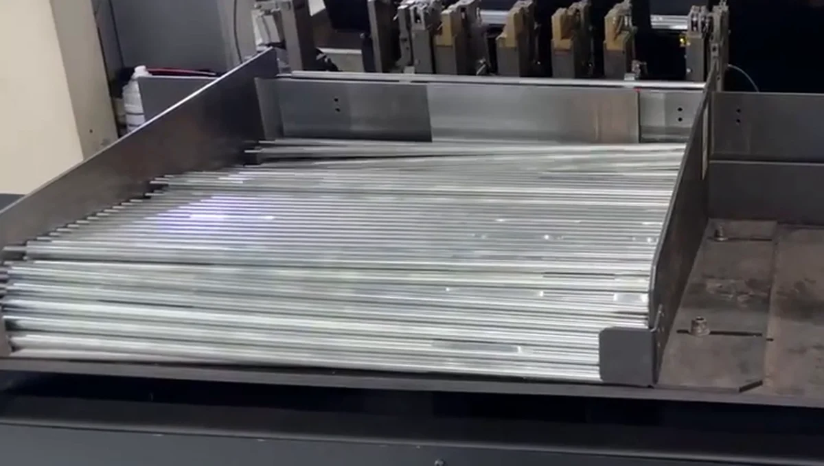
Το βίντεο δεν αποδεικνύει ότι ο δίσκος που εμφανίζεται καλύπτει κάθε δηλωμένο μήκος και διάμετρο. Το τελικό σύστημα τροφοδοσίας θα πρέπει να επικυρωθεί χρησιμοποιώντας το συντομότερο, μακρύτερη, μικρότερες και μεγαλύτερες πραγματικές παραλλαγές.
Περιστροφή και μέτρηση πολλών σημείων
Το εξάρτημα περιστρέφεται σύμφωνα με το συμφωνημένο σημείο αναφοράς, ενώ οι αισθητήρες επαφής ή οι αισθητήρες λέιζερ συλλέγουν την εκροή στις καθορισμένες διαμέτρους μέτρησης. Δύναμη ανιχνευτή, Το εύρος του αισθητήρα και το φιλτράρισμα πρέπει να επιλέγονται για την επιφάνεια και την ταχύτητα περιστροφής. Τραχύτητα επιφάνειας, Το σφάλμα στρογγυλότητας ή η μόλυνση δεν πρέπει να εκλαμβάνεται ως κάμψη άξονα.

Οι 1–5 θέσεις ευθυγράμμισης πρέπει να χαρτογραφηθούν χωριστά από τα σημεία μέτρησης. Ένας ανιχνευτής μπορεί να μετρήσει ένα λειτουργικό ημερολόγιο ενώ η ασφαλέστερη θέση πιεστηρίου βρίσκεται σε ένα γειτονικό, ισχυρότερο τμήμα. Ο ελεγκτής πρέπει να χρησιμοποιήσει τη σχέση σχεδίασης μεταξύ αυτών των σημείων αντί να υποθέσει ότι κάθε μετρούμενο μέγιστο μπορεί να πατηθεί απευθείας.
Υπολογισμός κάμψης και ελεγχόμενη υπερβολική κάμψη
Το στοιχείο ελέγχου προσδιορίζει το κυρίαρχο διάνυσμα κάμψης και επιλέγει μια ακολουθία διόρθωσης. Η υπερβολική κάμψη μετακινεί το τμήμα πέρα από την επιθυμητή τελική θέση, έτσι ώστε το ελαστικό ελατήριο να το επαναφέρει πιο κοντά στον στόχο. Τα αρχικά όρια εγκεφαλικού επεισοδίου πρέπει να είναι συντηρητικά, ειδικά κοντά στο HB 302 τέλος της σειράς υλικών, και εξευγενισμένα από τη μετρούμενη απόκριση αντιπροσωπευτικών δειγμάτων.
Όπου είναι διαθέσιμη η μέτρηση δύναμης, Η συμπεριφορά δύναμης/μετατόπισης μπορεί να παρέχει ένα επιπλέον όριο μη φυσιολογικής απόκρισης. Το σύστημα θα πρέπει να σταματήσει εάν η απόκριση διαφέρει ουσιαστικά από την επικυρωμένη συνταγή, επιτυγχάνεται ο μέγιστος αριθμός διόρθωσης ή το τμήμα αποτυγχάνει να συγκλίνει με ασφάλεια.
Πλήρης Επαναμέτρηση και Τελική Απόφαση
Μετά από κάθε ενέργεια τύπου, όλα τα απαιτούμενα σημεία μέτρησης ελέγχονται ξανά στο ίδιο σημείο αναφοράς. Μια τοπική βελτίωση δεν αρκεί εάν μια άλλη διάμετρος κινείται εκτός ανοχής. Η τελική απόφαση ΟΚ απαιτεί το πλήρες σύνολο καθορισμένων σημείων για να πληροί το κριτήριο του πελάτη.
Τα αρχεία ποιότητας μπορεί να περιλαμβάνουν αναγνωριστικό μοντέλου, εισερχόμενη και τελική εκκαθάριση, αποτελέσματα σημείων μέτρησης, διορθωτικές θέσεις/καταμέτρηση, έκδοση συνταγής και τελική ταξινόμηση. The scope should match the customer's traceability requirement rather than adding data fields that will not be used.
Αντικατάσταση υφιστάμενου εξοπλισμού: Χρησιμοποιήστε ένα ελεγχόμενο σημείο αναφοράς
Ο πελάτης αξιολογεί μια εναλλακτική λύση στον υπάρχοντα εξοπλισμό ισιώματος. Δεν είναι τεχνικά ορθό να διεκδικήσετε την ίδια απόδοση ή μια σταθερή μείωση τιμής κατά δύο τρίτα χωρίς να συγκρίνετε τα ίδια τεμάχια εργασίας, μέθοδος μέτρησης, εύρος αυτοματισμού, υποστήριξη εργαλείων και κύκλου ζωής.
| Στοιχείο αναφοράς | Απαιτούμενη σύγκριση |
|---|---|
| Σετ τεμαχίου εργασίας | Το ίδιο συντομότερο/μακρύτερο, μικρότερα/μεγαλύτερα και χειρότερα δείγματα |
| Δεδομένο και μετρητή | Ίδια υποστήριξη, περιστροφή, ανιχνευτές και υπολογισμός αποδοχής |
| Ποιότητα | Τελική εξάντληση σε κάθε απαιτούμενο σημείο; κατάσταση επιφάνειας και ρωγμής |
| Διαδικασία | Αριθμός διόρθωσης, χρόνος κύκλου, επαναληψιμότητα και ποσοστό NOK |
| Αλλαγή | Εργαλεία, συνταγή και χρόνος χειριστή για όλα τα μοντέλα |
| Αυτοματοποίηση | Σίτιση, διαλογή, ιχνηλασιμότητα και διεπαφές εγκαταστάσεων που περιλαμβάνονται και στα δύο πεδία |
| Κόστος ιδιοκτησίας | Εξοπλισμός, εργαλεία, εγκατάσταση, εκπαίδευση, συντήρηση, υποθέσεις ανταλλακτικών και χρόνου διακοπής λειτουργίας |
| Αποδοχή | Γραπτά κριτήρια FAT/SAT αντί για μη υποστηριζόμενη γενική δήλωση ισοδυναμίας |
Συνιστώμενη διαμόρφωση κελιών
| Μονάδα μέτρησης | Προτεινόμενη Απαίτηση | Γιατί Χρειάζεται |
|---|---|---|
| Έννοια μηχανής | Αυτόματη περιστρεφόμενη κυψέλη πίεσης-ισιώματος | Διόρθωση κλειστού βρόχου για εκκένωση άξονα πολλαπλών σημείων |
| Φάκελος τεμαχίου εργασίας | Μήκος 183–720 mm; με μέτρηση OD 14–23,5 mm; άλλα ΟΔ μέχρι 28.5 mm | Καλύπτει την αναφερόμενη οικογένεια έργου, υπόκειται σε αναθεώρηση σχεδίων |
| Σύστημα Μετρήσεων | Μέτρηση εξάντλησης επαφής πολλαπλών σημείων ή λέιζερ | Ημερομηνία αγώνα, απαιτήσεις διαδρομής επιφάνειας και αισθητήρα |
| Περιστροφή / Δεδομένο | Κέντρα, κυλίνδρους ή στηρίγματα περιοδικών που επιλέγονται από το σχέδιο | Επαναλαμβανόμενη μέτρηση γωνιακής κάμψης |
| Μονάδα ισιώματος | Λεπτά ελεγχόμενη σερβο/ηλεκτρομηχανική/υδραυλική πρέσα ανάλογα με το μέγεθος | Διαχειριστείτε την επαναφορά στο HB 241–302 |
| Υποστηρίζει και Punch | Ευκανόνιστος, περίγραμμα, επιφανειακά προστατευτικά εργαλεία | Καλύψτε το εύρος μήκους/διαμέτρου και προστατέψτε το Ra 1.25 μm επιφάνειες |
| Στρατηγική Ελέγχου | Συνταγές, κάμψη διάνυσμα, προσαρμοστική διαδρομή και όρια σκληρής επανάληψης | Διορθώστε 1–5 σημεία χωρίς ανεξέλεγκτο επαναλαμβανόμενο πάτημα |
| Σίτιση | Δίσκος, γεμιστήρα ή χειροκίνητη φόρτωση με βάση επικυρωμένο takt και μείγμα ανταλλακτικών | Ταιριάξτε τη ροή παραγωγής χωρίς να υποθέσετε ότι δεν υποστηρίζεται αυτοματισμός |
| Δεδομένα Ποιότητας | Πριν/μετά αποτελέσματα και ιστορικό διορθώσεων όπως απαιτείται | Βαθμολόγηση επιδόσεων, αποδοχή και ιχνηλασιμότητα |
| Ασφάλεια | Φρούρηση, συμπλέξεις, συναγερμοί υπερφόρτωσης και μη φυσιολογικών μετρήσεων | Προστατέψτε τον χειριστή, μέρος και εργαλεία |
Επικύρωση έργου πριν από την τελική προσφορά
Τα αντιπροσωπευτικά δείγματα πρέπει να καλύπτουν το ελάχιστο και το μέγιστο μήκος, όλες οι παραλλαγές διαμέτρου μέτρησης, κανονική και μέγιστη εισερχόμενη εξάντληση, HB 241 και ΗΒ 302 υλικές συνθήκες, κάθε σχετική παρτίδα θερμικής επεξεργασίας και όλες οι μεταβάσεις τμημάτων. Η αναφορά δοκιμής πρέπει να καταγράφει το δεδομένο, κάθε σημείο μέτρησης, εισερχόμενη αξία, θέση/μέτρηση διόρθωσης, τελική αξία, κατάσταση επιφάνειας και χρόνος κύκλου.
The customer's inspection gauge and the machine should be correlated before the 0.2 Η τιμή mm γίνεται εγγύηση αποδοχής. Εάν το πραγματικό τεμάχιο εργασίας είναι κοίλο ή περιέχει κρυφά χαρακτηριστικά που δεν εμφανίζονται στα τρέχοντα δεδομένα, το σχέδιο και η ανασκόπηση του δείγματος πρέπει να αναθεωρήσουν την αξιολόγηση εργαλείων και κινδύνου πριν από την τελική επιλογή του μηχανήματος.
Πληροφορίες που απαιτούνται για μια πρόταση ισιώματος από χάλυβα άξονα και ράβδου
Δώστε το τελικό όνομα και την εφαρμογή του τεμαχίου εργασίας, σχέδιο, πρότυπο υλικού και πιστοποιητικό, στάδιο σκληρότητας και θερμικής επεξεργασίας, όλες οι διαμέτρους και οι θέσεις χαρακτηριστικών, κεντρικές τρύπες / περιοδικά, διανομή εισερχόμενων εκροών, στόχο σε κάθε σημείο μέτρησης, βάση δεδομένων και μετρητή, εγκεκριμένες ζώνες υποστήριξης/πίεσης, απαίτηση προστασίας επιφάνειας, στόχος, ετήσιος όγκος, κατεύθυνση φόρτωσης και αντιπροσωπευτικά δείγματα εξαρτημάτων.
Αυτές οι είσοδοι επιτρέπουν στην ομάδα λύσης να επιβεβαιώσει εάν το εξάρτημα είναι συμπαγής άξονας/ράβδος ή κοίλος σωλήνας, επιλέξτε τη μέθοδο μέτρησης και ευθυγράμμισης, μέγεθος της δύναμης/εγκεφαλικού επεισοδίου και των εργαλείων, και να δημιουργήσετε ένα αντικειμενικό σημείο αναφοράς FAT/SAT.
FAQ
Είναι ο στόχος 0.2 χιλιοστά ευθύτητα ή ακτινική διαρροή?
Η τρέχουσα είσοδος το ονομάζει εξάντληση εξωτερικής διαμέτρου. Το σχέδιο πρέπει να επιβεβαιώνει το δεδομένο, θέσεις μέτρησης και μέθοδος περιστροφής. Δεν θα πρέπει να ξαναγραφτεί ως ευθύτητα χωρίς αυτά τα στοιχεία.
Μπορεί το μηχάνημα να μειώσει τη μέγιστη εξάντληση από 0.5 να 0.2 mm?
Αυτός είναι ο στόχος του έργου, δεν είναι ακόμη επαληθευμένο αποτέλεσμα. Η σκοπιμότητα εξαρτάται από το δεδομένο, γεωμετρία, σκληρότητα, κατανομή κάμψης, εγκεκριμένες ζώνες διόρθωσης και απόκριση δοκιμής δείγματος.
Μπορεί ένα μηχάνημα να χειριστεί μήκη από 183 να 720 mm?
Δυνητικά, εάν η υποστήριξη ταξιδεύει, θέσεις μέτρησης, άξονας τύπου, σύστημα τροφοδοσίας και συνταγές καλύπτουν όλο το φάσμα. Οι παραλλαγές τελικού σημείου πρέπει να περιλαμβάνονται στην επικύρωση.
Πώς είναι το Ra 1.25 μm προστατευμένη επιφάνεια?
Η λύση χρησιμοποιεί καθαρά στηρίγματα με περίγραμμα, ελεγχόμενη δύναμη ανιχνευτή και ζώνες επαφής/πίεσης εγκεκριμένες για σχέδιο. Η επιφανειακή επιθεώρηση παραμένει μέρος του σχεδίου αποδοχής δειγματοληπτικών δοκιμών.
Γιατί είναι σημαντικά 1–5 σημεία ευθυγράμμισης?
Υποδεικνύουν ότι διαφορετικά μοντέλα ή προφίλ κάμψης μπορεί να απαιτούν διαφορετικές θέσεις διόρθωσης. Το μηχάνημα πρέπει να επαναμετρήσει όλες τις ελεγχόμενες διαμέτρους μετά από κάθε διόρθωση γιατί η βελτίωση ενός σημείου μπορεί να αλλάξει ένα άλλο.
Το βίντεο αποδεικνύει ότι αυτά είναι σταθερά; 25 άξονες από χάλυβα?
Οχι. Εμφανίζει κυλινδρικό κοντάκι και σταθμό ισιώματος, αλλά τα άκρα και το υλικό δεν είναι αναγνωρίσιμα. The article's shaft/bar specification comes from the project data, όχι από οπτική εικασία για το βίντεο.
Μπορεί αυτός ο εξοπλισμός να παρουσιαστεί ως ίσος με έναν υπάρχοντα ανταγωνιστή σε σταθερή χαμηλότερη τιμή?
Μόνο μετά από ένα ελεγχόμενο σημείο αναφοράς του ίδιου δείγματος και ένα συγκρίσιμο εμπορικό πεδίο. Ποιότητα, χρόνος κύκλου, εργαλεία, αυτοματοποίηση, Το κόστος υπηρεσίας και κύκλου ζωής πρέπει να συγκριθεί χρησιμοποιώντας γραπτά κριτήρια αποδοχής.
Σύναψη
Αυτό το έργο χαλύβδινου άξονα/ράβδου καθορίζεται από τη μέτρηση εξόδου πολλαπλών διαμέτρων, 1–5 ελεγχόμενες θέσεις διόρθωσης, HB 241–302 backback και προστασία του Ra 1.25 μm επιφάνεια. Μια αξιόπιστη λύση πρέπει να μετρήσει ολόκληρο το εξάρτημα στο λειτουργικό δεδομένο, διορθώστε μόνο τις εγκεκριμένες ζώνες και επαληθεύστε κάθε σημείο μετά από κάθε ενέργεια πατήματος.
For a steel shaft and bar application like this one, procurement teams usually pair the manual vs automatic selection logic with the Θήκη ROI για αυτόματο ίσιωμα before shortlisting vendors.
Στείλτε τις ζωγραφιές σας, πιστοποιητικά υλικού/σκληρότητας, εισερχόμενα δεδομένα εκκαθάρισης, 0.2 mm ορισμός αποδοχής, μείγμα ανταλλακτικών και πληροφορίες δείγματος για ανασκόπηση σκοπιμότητας και συγκριτικής αξιολόγησης. Η τελική απόδοση θα πρέπει να συμφωνηθεί μέσω αντικειμενικών κριτηρίων FAT/SAT αντί για μη επαληθευμένη ισοδυναμία ή δηλώσεις τιμών.