
Leitspindeln wandeln in Aktoren Drehbewegungen in kontrollierte Linearbewegungen um, Positionierungssysteme, kompakte Automatisierungs- und Schrittmotorbaugruppen. Eine kleine Biegung kann einen Rundlauf verursachen, ungleichmäßige Bewegung der Mutter, Lärm, zusätzliche Lagerbelastung oder Montageschwierigkeiten. Denn das Gewinde ist sowohl Funktionsfläche als auch schwierige Kontaktgeometrie, Eine Leitspindel kann nicht wie eine einfache Rundstange behandelt werden.
Diese vorgeschlagene Lösung zum Richten der Leitspindel kombiniert eine wiederholbare Bezugsunterstützung, Rotationsmessung, geschützte Punktpressung und vollständige Neumessung. Es basiert auf Kundeninformationen für zwei sehr unterschiedliche mögliche Teilefamilien: ein kurzer Ø6,35 × 75 mm-Schraube und vier Probestücke mit einem Durchmesser von 3,5 angegeben × 508 mm. Durch diese Abmessungen ergeben sich Längen-Durchmesser-Verhältnisse von ca 11.8 Und 145.1, Daher erfordern sie separate Machbarkeitsfenster und nicht ein angenommenes Maschinenrezept.
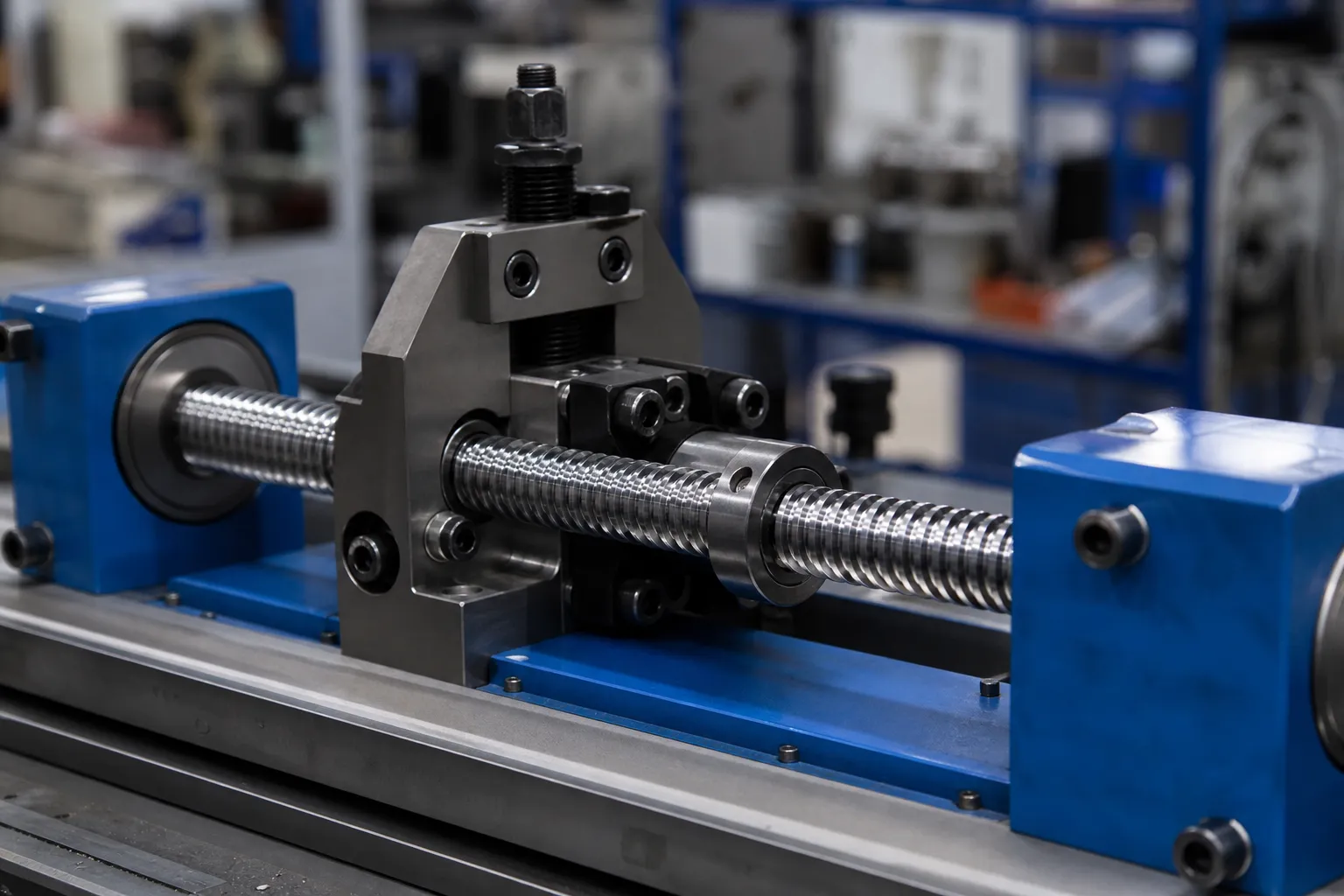
*Quell-Video-Frame.* Es zeigt eine Gewindeschraube in einer Kompaktstation, legt aber keine der Kundengeometrien fest, automatische Beladung oder eine Produktionsmöglichkeit.
Anforderungen an ein Leitspindelprojekt
Der Kunde beschreibt die Anwendung als Schrittmotor-Leitspindel und gibt eine elektrische Nennleistung des Motors an 2.33 VDC bei 1.5 A. Diese Bewertung kann bei der Identifizierung der Baugruppe hilfreich sein, es definiert jedoch nicht die Wellensteifigkeit, Richtkraft, Messbezugspunkt oder akzeptabler Rundlauffehler. Der Richtvorschlag muss auf der Schraubenzeichnung basieren, Material, Wärmebehandlung, Fadenform, Prozessstadium und Maßtoleranz.
Die Zeile „vier Stück, Ø3,5 × 508 „mm“ gilt als Mustermenge für eine zweite Geometrie, bis der Kunde etwas anderes bestätigt. Es sollte nicht automatisch mit dem Ø6,35 zusammengeführt werden × 75 mm-Teil oder verwendet, um eine universelle Maschinenpalette zu beanspruchen.
| Projektelement | Kundeneingabe / Status |
|---|---|
| Werkstück | Leitspindel für eine Schrittmotoranwendung |
| Kandidatenfamilie A | Ø6,35 mm × 75 mm; L/D ≈ 11.8 |
| Kandidat Familie B | Vier gemeldete Proben, Ø3,5 mm × 508 mm; L/D ≈ 145.1 |
| Motorbewertung | 2.33 VDC bei 1.5 A; Nur Baugruppenidentifikation, keine Richteingabe |
| Aktuelle Ausrüstung | Der Kunde meldet die frühere Verwendung von Galdabini-Geräten |
| Material / Härte | Wird noch bestätigt |
| Gewindeform / Führen | Wird noch bestätigt |
| Eingehende Kurve | An repräsentativen Proben zu messen |
| Letzte Anforderung | Geradheit oder TIR, Bezugs- und Messpositionen müssen bestätigt werden |
| Vorgeschlagene Methode | Rotationsmessung mit geschlossenem Regelkreis und geschütztes Punktpressrichten |
Warum die Familien mit zwei Größen separate Machbarkeitsfenster benötigen
Der Durchmesser hat einen starken Einfluss auf die Biegesteifigkeit, während Längenänderungen sowohl das Verhalten als auch die Messempfindlichkeit unterstützen. Der 75 Die mm-Schraube ist kompakt genug, um den Zugang zum Gerät zu ermöglichen, Kurze Stützweiten und die Lage der Merkmale können das Design dominieren. Der 508 mm-Schraube ist im Verhältnis zu ihrem Durchmesser extrem schlank, Daher kann sich sein scheinbarer Wert mit dem Abstand der Stützen ändern, Haltung, Sondenkraft und Eigengewicht.
Die beiden Familien passen möglicherweise immer noch in eine modulare Maschinenplattform, aber diese Schlussfolgerung erfordert Stichprobentests. Sie benötigen möglicherweise unterschiedliche Unterstützungen, Sondenbereiche, Kontaktgeometrie der Presse, Korrekturschritte, Belastungsmethoden und sogar unterschiedliche Messausrichtungen.
| Technischer Faktor | Ø6,35 × 75 mm Familie | Ø3,5 × 508 mm Familie |
|---|---|---|
| Geometrie | Kurzer Gewindeschaft | Ultraschlanker Gewindeschaft |
| Primäres Vorrichtungsrisiko | Begrenzter Platz für Stützen, Sonde und Presswerkzeug | Selbstablenkung und instabile Langstreckenunterstützung |
| Messempfindlichkeit | Merkmalsposition und Spannfutter-/Stützfehler | Stützposition, Sondenkraft, Körperhaltung und Umweltstörungen |
| Korrekturstrategie | Kurzfristig, Feinverschiebungspunktkorrektur | Unterstützung mehrerer Positionen und sehr kleine schrittweise Korrektur nach Machbarkeitstest |
| Handhabung | Möglicherweise ist eine manuelle Verschachtelung oder eine kompakte automatische Zuführung möglich | Wahrscheinlich sind eine Führung über lange Teile und ein Anti-Tangle-Handling erforderlich |
| Gemeinsame Rezeptannahme | Nicht erlaubt | Nicht erlaubt |
Geradlinigkeit, Rundlauf und Funktionsdatum
Geradheit und Rundlauf sind nicht austauschbar. Die Geradheit beschreibt die Abweichung eines Elements von einer idealen Geraden. Der Radialschlag oder der angezeigte Gesamtschlag wird gemessen, während sich das Teil um definierte Referenzen dreht, und hängt daher vom ausgewählten Bezugspunkt ab. Die Unterscheidungen werden ausführlicher behandelt in Geradheit der Welle, Rundlauf und TIR.
Für eine Präzisionsschraube, Der funktionale Bezug bezieht sich häufig auf Lagerzapfen, Die Unterstützung endet, Mittelpunkte oder ein anderes Zeichnungsdatum. THK beschreibt die Messung des Rundlaufs der Spindelwelle relativ zur Stützachse, einschließlich der Abstützung auf Zapfenabschnitten und der Ablesung an mehreren axialen Positionen während der Drehung der Welle. KURODA listet außerdem den Lagermontageschlag und den Gesamtschlag oder die Krümmung der gesamten Spindelwellenmitte unter den Prüfpunkten für Kugelgewindetriebe auf. Diese Grundsätze zeigen, warum ein Angebot nicht nur auf Außendurchmesser und Länge basieren kann.
| Annahmegegenstand | Definition vor Garantie erforderlich |
|---|---|
| Kontrollierte Charakteristik | Geradheit der Welle, Radialschlag, TIR oder Montagefehler |
| Datum | Lagerzapfen, Zentren, Stützenden oder zeichnungsdefinierte Referenz |
| Messen von Positionen | Exakte glatte Durchmesser, Mutternumfang oder spezielle Messpositionen |
| Messhaltung | Horizontal, vertikaler oder zeichnungsangepasster Auflagezustand |
| Sondenmethode | Kontaktkraft, Spitzengeometrie, Drehzahl und Filterung |
| Endgültige Grenze | Numerische Toleranz und Eichkorrelationsmethode |
| Oberflächenakzeptanz | Zulässige Markierungen auf Zeitschriften, Gewinde und nichtfunktionale Bereiche |
Warum die Gewindeoberfläche den Prozess verändert
Ein spiralförmiges Gewinde liefert nicht das gleiche Signal wie ein glatter zylindrischer Zapfen. Eine direkt auf der Spitze platzierte Sonde kann der Gewindegeometrie folgen, Oberflächenvariation oder neigungsbedingte Bewegung statt nur der Wellenmittellinie. Die Messung an einem glatten Lagerzapfen oder einem zugelassenen Referenzdurchmesser wird bevorzugt, wenn sie den funktionalen Bezugspunkt darstellt.
Wenn die Zeichnung keine geeignete glatte Messfläche vorsieht, Für die Lösung ist möglicherweise eine spezielle Überwurfmutter erforderlich, eine Messung des Mutterumfangs, eine optische Methode oder ein anderes validiertes Messgerätekonzept. The method must be proven against the customer's final inspection; Es sollte nicht nur aus einem Videobild ausgewählt werden.
Ebenso wichtig ist der Gewindeschutz bei der Korrektur. Roton empfiehlt das Richten mit einer Presse für Leitspindeln und warnt davor, dass Rollrichtmethoden für glatte Stangen das Gewinde beschädigen können. Seine Führung erfordert eine kontrollierte Stößelbewegung und weiche Schuhe an Stößel und Stützen. Das endgültige Kontaktmaterial und Profil muss noch passend zum eigentlichen Schraubenmaterial ausgewählt werden, Härte, Zieleinlauf und erlaubte Kontaktzonen.
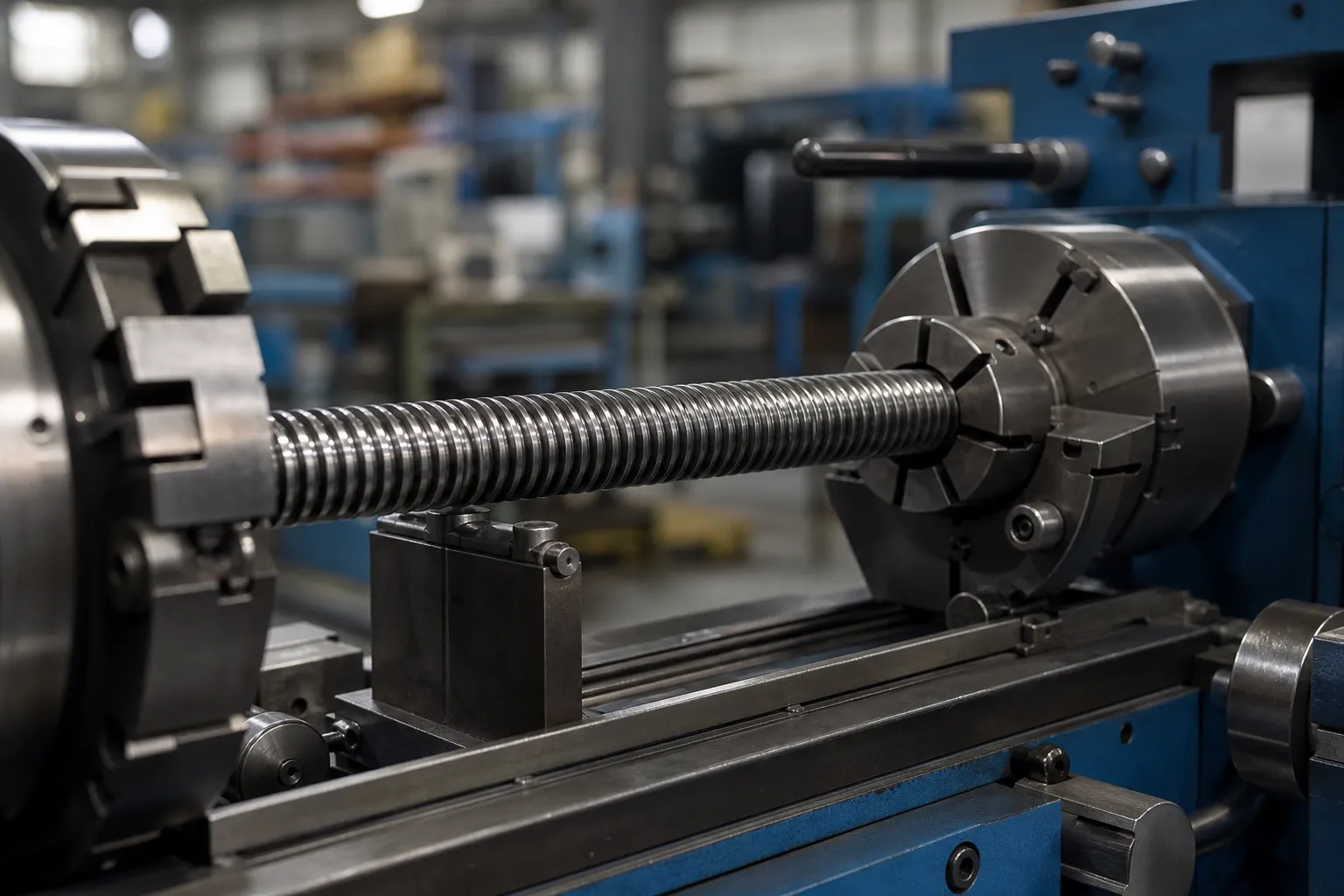
*Quell-Video-Frame.* Datumsauswahl, Kontaktstellen und Messrelevanz müssen anhand der genehmigten Zeichnung bestätigt werden.
Empfohlene Richtmethode
Das bevorzugte Ausgangskonzept ist das automatische Punktpressrichten mit Rundlaufmessung. Das Teil wird auf einem vereinbarten Datum gestützt, gedreht, um die Größe der Biegung und die Winkelrichtung zu ermitteln, indexiert auf den Korrekturwinkel, in kontrollierten Schritten gedrückt und dann erneut gemessen.
Dieser Ansatz ermöglicht es dem Werkzeug, empfindliche Gewindespitzen zu vermeiden, Schultern, Hinterschnitte und fertige Zapfen. Es unterstützt auch modellspezifische Grenzwerte für eine kurze Schraube und eine ultraschlanke Schraube. Für einige gleichmäßige Rohlinge vor der Gewindeerzeugung kann eine kontinuierliche Walzenrichtmaschine geeignet sein, Es sollte jedoch nicht davon ausgegangen werden, dass es für eine fertige Leitspindel geeignet ist. Die umfassenderen Auswahlkriterien sind in zusammengefasst Pressrichten versus Rollenrichten.
MAE identifiziert sich öffentlich lange, schlanke Kugelumlaufspindeln als Präzisionsrichtanwendungen, while Roton's application guidance favors press-type correction for threaded screws. Diese Referenzen unterstützen das Prozessprinzip, Sie beweisen jedoch nicht, dass eine der gemeldeten Kundengrößen bereits einen StraighteningTech-Mustertest bestanden hat.
Vorgeschlagener Richtprozess mit geschlossenem Kreislauf
Das zugehörige 24-Sekunden-Video zeigt eine Gewindespindel in kompakter Rotation, Stütz- und Korrekturstation. Es bestätigt das Vorhandensein eines fertigen Threads und eines Punktkorrekturkonzepts. Es ist kein Schrittmotor abgebildet, die angegebenen Abmessungen, automatisches Laden, ein kompletter Produktionszyklus, die endgültige Toleranz oder die vier langen Musterstücke.
| Schritt | Verfahren | Hauptsteuerung |
|---|---|---|
| 1 | Identifizieren Sie die Teilefamilie und laden Sie das Rezept | Verhindern Sie das 75 mm und 508 mm Familien davon abhalten, ungeprüfte Einstellungen zu teilen |
| 2 | Laden Sie die blanke Schraube oder die zugelassene Baugruppe | Prozessstufe bestätigen und Motorlager oder Kupplungen schützen |
| 3 | Legen Sie den funktionalen Bezug fest | Verwenden Sie von der Zeichnung genehmigte Zeitschriften, Zentren oder spezielle Unterstützungseinrichtungen |
| 4 | Drehen und messen | Zeichnen Sie die Größe der Biegung und die Winkelposition an definierten axialen Punkten auf |
| 5 | Validieren Sie das Signal | Erkennen Sie threadbezogene Variationen, instabiler Träger oder übermäßiger Sondeneinfluss |
| 6 | Stütz- und Presspositionen auswählen | Gewindeschäden vermeiden, schwache Übergänge und geschützte Oberflächen |
| 7 | Wenden Sie eine kontrollierte Korrektur an | Verwenden Sie eine begrenzte Verschiebung und ein validiertes Kraft-/Wegfenster |
| 8 | Alle erforderlichen Punkte erneut messen | Bestätigen Sie die Reaktion anhand des gleichen Datums und der gleichen Stützbedingung |
| 9 | In Grenzen wiederholen oder NIO einstufen | Stoppen Sie bei der Korrekturzählung, Gewalt, Hub- oder Konsistenzgrenzen |
| 10 | Ergebnis aufzeichnen und entladen | Behalten Sie bei Bedarf Vorher-/Nachher-Werte und Rezeptdaten bei |
Lade- und Prozessphase
Der bevorzugte Herstellungsschritt ist normalerweise die blanke Schraubenwelle, bevor der Motor zusammengebaut wird, Denn beim Pressen einer fertigen Baugruppe kann es zu einer Belastung der Motorlager kommen, Kupplung oder Rotor. Wenn der Kunde speziell eine Rundlaufkorrektur des montierten Motors und der Spindel benötigt, Die Vorrichtung und die Abnahmemethode müssen rund um die Baugruppe neu gestaltet und hinsichtlich der Lagerlast validiert werden.
Datumsunterstützung und Erstmessung
Die Welle wird auf den vereinbarten Referenzen abgestützt und in einem kontrollierten Zyklus gedreht. Für den Ø3,5 × 508 mm-Familie, Auflagepunkte und Antastkraft müssen Bestandteil der Messvorgabe sein. Ein Messwert, der mit einer Stützanordnung ermittelt wurde, kann ohne Korrelation nicht direkt mit einem Messwert verglichen werden, der in einer anderen Haltung ermittelt wurde.
Signalvalidierung
Die Steuerung sollte inkonsistente Messwerte ablehnen, bevor ein Pressbefehl erteilt wird. Mögliche Ursachen sind verunreinigte Träger, ein lockeres Futter, eine ungeeignete Sondenspitze, direkte Nachführung der Gewindegeometrie oder Selbstauslenkung des ultraschlanken Schafts. Eine Plausibilitätsprüfung und Wiederholungsmessung sind sicherer, als jede Spitze als Krümmung zu betrachten.
Sichere Stütz- und Korrekturposition
Zulässige Kontaktzonen sind der Zeichnung zu entnehmen. Fertige Fadenkämme, scharfe Fadenausläufe, Unterschneidungen, Schultern und Auflageflächen können geschützt oder eingeschränkt sein. Weich, Konturierte und austauschbare Stütz-/Stößeleinsätze können Markierungen reduzieren, Ihr Material muss jedoch mit dem Werkstück kompatibel sein und auf Verschleiß geprüft werden.
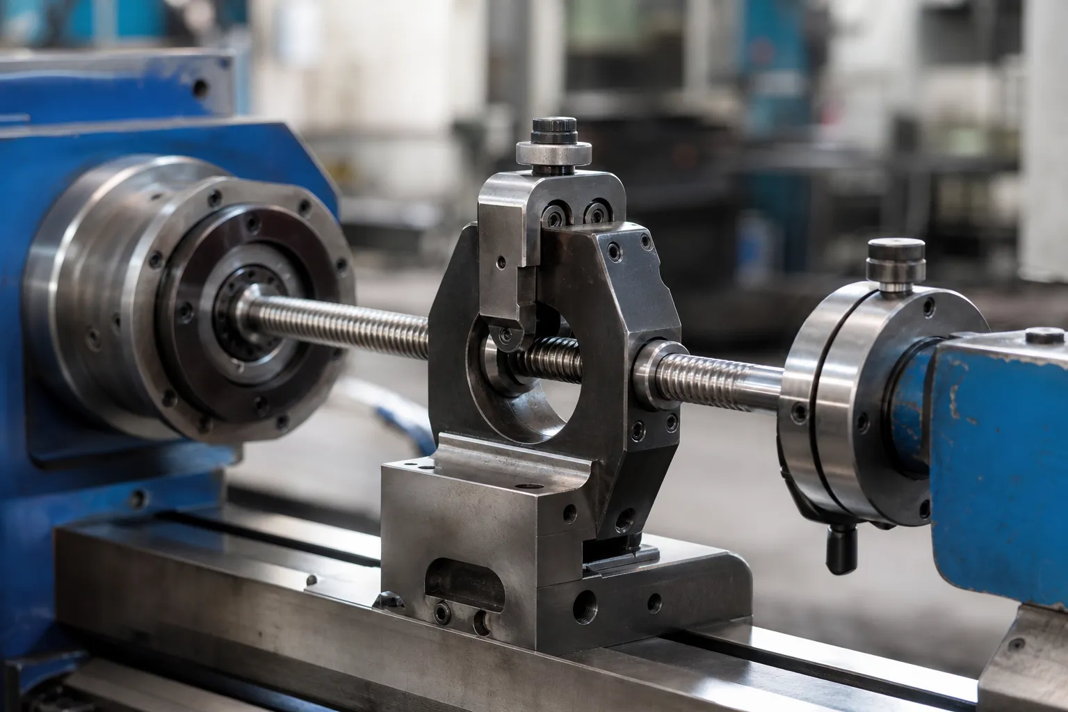
*Quellvideo-Frame.* Es veranschaulicht lediglich ein Punktkorrekturkonzept; Rillenschutz und Kraftgrenzen erfordern eine repräsentative Probenvalidierung.
Kontrollierte Korrektur und Rückfederung
Das Richten erfordert ein kontrolliertes Überbiegen, damit die elastische Rückfederung den Schaft näher an das Ziel zurückbringt. Die erforderliche Verschiebung ist kein universeller Prozentsatz. Es kommt auf den Materialzustand an, Durchmesser, lokale Gewinde-/Wurzelgeometrie, Stützweite und eingehende Biegung. Die anfängliche Korrektur muss daher konservativ sein und anhand der gemessenen Probenreaktion verfeinert werden.
Nachmessung und Sortierung
Nach jeder Korrektur, Alle erforderlichen Punkte werden erneut unter Verwendung des gleichen Bezugspunkts und der gleichen Stützbedingung gemessen. Eine Teilabnahme erfolgt nur, wenn die vereinbarte Beschaffenheit innerhalb der Toleranz liegt. Ein Teil, das die validierte Kraft erreicht, Schlaganfall, Der Zyklus- oder Messkonsistenzgrenzwert wird als NIO oder technische Überprüfung klassifiziert, anstatt wiederholt gedrückt zu werden.
Ultraschlank Ø3,5 × 508 mm Technische Kontrollen
Das L/D-Verhältnis beträgt ca 145.1 macht diese Familie zum beherrschenden Risiko im aktuellen Informationspaket. Die Maschine muss die tatsächliche permanente Biegung von der durch die Stützanordnung verursachten Durchbiegung unterscheiden, Schwerkraft, Kontaktkraft oder Handhabung. Während des Ladens können Führungen für lange Teile erforderlich sein, Sie müssen sich jedoch während der Messung wiederholt lösen oder positionieren, damit sie den natürlichen Schaftzustand nicht verdecken.
| Risiko | Möglicher Effekt | Validierungskontrolle |
|---|---|---|
| Eigengewicht zwischen den Stützen | Offensichtliche Biegeveränderungen je nach Stützabstand oder Haltung | Definieren Sie Stützstandorte und korrelieren Sie die Produktionsstärke |
| Kontaktkraft der Sonde | Der Sensor verändert die Position, die er misst | Sonde mit geringer Kraft oder validierte berührungslose Methode |
| Langer, nicht unterstützter Schwanz | Vibration und instabile Winkelanzeige | Zusätzliche kontrollierte Stützen oder eine alternative Ausrichtung |
| Kleines Korrekturfenster | Ein Strich kehrt die Biegung um oder lokalisiert sie | Feine Verschiebungsauflösung und stufenweise Korrekturen |
| Thread-Kontakt | Kammschaden oder neigungsbezogenes Messsignal | Geschützte Werkzeuge und zeichnungsgeprüfte Messmethode |
| Handhabung | Verwicklung, Kratzer oder Neubiegung vor der Messung | Geführtes Laden, kontrollierte Lagerung und Teiletrennung |
Empfohlene Maschinen- und Zellenkonfiguration
| Modul | Vorgeschlagene Anforderung | Projektgrenze |
|---|---|---|
| Maschinenkonzept | Präzise automatische Spitzenrichtstation | Die endgültige Plattform wird ausgewählt, nachdem beide Familien getestet wurden |
| Messung | Kontaktarmes oder validiertes berührungsloses Auslaufsystem mit geringer Kraft | Muss die vereinbarte Bezugs- und Messgerätemethode reproduzieren |
| Drehung | Präzisionsfutter, Zentren oder Zeitschriftenunterstützungen | Es wird nicht davon ausgegangen, dass der Faden allein der Bezugspunkt ist |
| Unterstützt | Einstellbar, konturiert, austauschbare Kontakte | Separate Layouts für kurze und ultraschlanke Schrauben |
| Drücken Sie auf Einheit | Servoelektrische Feinverstellung oder hydraulische Präzisionskorrektur | Aus Proben ermittelter Kraft- und Hubbereich |
| Werkzeuge | Gegebenenfalls weiche/geschützte Stößel- und Stützeinsätze | Material- und Kontaktmarkierungen bedürfen einer Genehmigung |
| Kontrollen | Modellrezepte, Plausibilitätsprüfungen und Closed-Loop-Korrektur | Kein gemeinsames Rezept ohne Validierung |
| Laden | Handbuch, Magazin oder automatische Handhabung | Ausgewählt aus der Teilestabilität, Lautstärke und Takt |
| Daten | Eingehende/endgültige Lesungen, Korrekturanzahl und OK/NOK | Durch Kundenanforderung definierter Rückverfolgbarkeitsgrad |
| Sicherheit | Bewachung, Verriegelungen, Alarme bei Überlastung und abnormalen Messwerten | Erforderlich für die Produktionskonfiguration |
Benchmarking eines Ersatzes für bestehende Geräte
Der Kunde meldet eine frühere Nutzung von Galdabini-Geräten und evaluiert eine alternative Quelle. Für einen verantwortungsvollen Vergleich sollte dieselbe repräsentative Probencharge verwendet werden, das gleiche Datum und die gleiche Stärke, die gleichen Akzeptanztoleranzen und die gleichen Oberflächenschädigungskriterien. Es sollte auch die Korrekturrate verglichen werden, Zykluszeit, Umstellung, falsche Ablehnungen, Wartungszugriff und Datenanforderungen.
Der Vorschlag sollte nicht den Anspruch erheben, dass ein Markenname „mit Galdabini gleichwertig“ sei, Foto oder Nenndurchmesserbereich. Die Gleichwertigkeit kann nur durch einen dokumentierten Benchmark oder ein FAT/SAT-Ergebnis für die vereinbarten Teile gestützt werden.
| Benchmark-Artikel | Erforderliche Nachweise |
|---|---|
| Messkorrelation | Gleiches Datum, Messpunkte und kalibrierter Messgerätevergleich |
| Endgültige Qualität | Vorher/Nachher-Ergebnisse für repräsentative Normal- und Worst-Case-Teile |
| Gewindeschutz | Visuell, Maß- und Funktionsabnahme nach dem Richten |
| Prozessfähigkeit | Ausreichende Probengröße, nachdem das Korrekturrezept stabil ist |
| Durchsatz | Zeitgesteuerter Zyklus inklusive Beladung, Iterationen, Entladen und normale Stopps |
| Umstellung | Demonstrierte Werkzeugausstattung und Rezeptwechsel für beide Größenfamilien |
| Zuverlässigkeit | Alarm, Überprüfung der Wartung und Wiederholbarkeit während der Erprobung oder Abnahme |
Projektvalidierung vor dem endgültigen Angebot
Repräsentative Proben sollten beide Geometrien abdecken, normale und ungünstigste eingehende Kurven, jeder Material- oder Wärmebehandlungszustand und alle relevanten Gewinde-/Zapfenvarianten. Bei jedem Versuch sollte der Supportzustand aufgezeichnet werden, Messbezugspunkt, eingehende Wellenform, Korrekturposition, Kraft/Hub, sofern verfügbar, Endergebnis, Korrekturanzahl und etwaige Oberflächeneffekte. Eine dokumentierte Richten des Muster-Test-Abnahmeplans sollte festlegen, wie aus diesen Ergebnissen eine Genehmigungsentscheidung wird.
Der Ø3,5 × 508 mm-Probenfamilien sollten vor Beginn der Korrekturversuche separat auf Wiederholbarkeit der Messungen untersucht werden. Wenn das Messgerät die Biegung des Teils nicht von der Stütze unterscheiden kann- oder sondeninduzierte Ablenkung, ein Richtergebnis kann nicht zuverlässig garantiert werden.
Erforderliche Informationen für einen Vorschlag zum Richten der Leitspindel
Bitte Schraubenzeichnung beifügen, Bestätigung, ob es sich bei den beiden Größen um separate Modelle handelt, Probenmenge und Jahresvolumen, Material und Härte, Gewindeform und Steigung, Wärmebehandlungs- und Bearbeitungsphase, Lager-Journal- und Zentrumsstandorte, eingehende Rundlaufverteilung, endgültiges Merkmal und Datum, zulässige Stütz-/Presszonen, geschützte Oberflächen, Phase der Motormontage, Ziel schlagen, Laderichtung und repräsentative Proben.
Diese Eingaben ermöglichen es dem Lösungsteam, die Messmethode auszuwählen, Unterstützungslayout, Presseauflösung, sicheres Korrekturfenster, Werkzeuge, Handhabungs- und Abnahmeplan, ohne allein anhand der Motorleistung oder des Videos raten zu müssen.
Technische Referenzbasis
- THK-Kugelumlaufspindelgenauigkeit und Montageflächenmessung beschreibt den Rundlauf relativ zur Trägerachse und die Messung an mehreren axialen Positionen.
- KURODA-Kugelumlaufspindel-Inspektionsanleitung listet den Rundlauf der Lagerbefestigung und die Gesamtkrümmung der Schraubenwelle unter den zeichnungsbasierten Prüfpunkten auf.
- Führung zum Richten der Roton-Leitspindel empfiehlt kontrollierte Pressricht- und Fadenschutzschuhe.
- MAE-Werkstückanwendungen identifiziert lange, schlanke Kugelumlaufspindeln als Präzisionsrichtanwendungen.
Diese Quellen unterstützen nur technische Prinzipien. They are not evidence of achieved results for the customer's reported parts.
FAQ
Kann eine Maschine beide Ø6,35 begradigen? × 75 mm und Ø3,5 × 508 mm Gewindespindeln?
Möglicherweise, wenn der Messbereich, unterstützt, Presseauflösung, Handhabungs- und Korrekturfenster decken beide Familien ab. Der L/D-Unterschied ist groß genug, dass dies mit separaten Werkzeugen und Stichprobenversuchen nachgewiesen werden muss, nicht allein aufgrund des Durchmessers angenommen.
Tut das 2.33 VDC bei 1.5 Die Motorleistung beeinflusst die Richtkraft?
NEIN. Es hilft bei der Identifizierung der Schrittmotorbaugruppe, definiert jedoch nicht das Schraubenmaterial, Biegesteifigkeit, Gewindegeometrie, Stützweite oder Richtkraft.
Sollte die Schraube vor oder nach der Motormontage gerichtet werden??
Die blanke Schraubenwelle ist die bevorzugte Ausgangsstufe, da sie die Übertragung der Korrekturlast auf Motorlager oder Kupplungen vermeidet. Eine Montagekorrektur ist nur mit einer speziellen Vorrichtung und einem genehmigten Lagerlast- und Rundlaufvalidierungsplan möglich.
Kann die Maschine direkt am Gewinde messen??
Nur mit einer für die Gewindeform und Endkontrolle validierten Methode. Glatte Tagebücher, Lagersitze, Zentren, ein Meisterverrückter, Der Mutterumfang oder eine geeignete optische Methode können eine zuverlässigere Funktionsreferenz liefern.
Wie werden Gewinde beim Pressen geschützt??
Das Rezept definiert genehmigte Stütz- und Presszonen, während konturierte austauschbare Kontakte die Last verteilen. Weiche Schuhmaterialien können geeignet sein, Das endgültige Material und die endgültige Geometrie müssen jedoch die Oberflächen- und Funktionsprüfung an tatsächlichen Schrauben bestehen.
Was beweist das Projektvideo??
Es zeigt eine Gewindespindel in einer kompakten Dreh-/Stütz-/Korrekturstation. Es beweist nicht die angegebenen Abmessungen, Motorbaugruppe, automatische Fütterung, Zykluszeit, Endtoleranz oder Langschraubenergebnis.
Kann garantiert werden, dass die alternative Maschine der vorhandenen Galdabini-Ausrüstung gleichwertig ist??
Nur nach einem Benchmark mit derselben Stichprobe und demselben Datum, Messgerät, Toleranz, Oberflächenkriterien und Produktionsbedingungen. Ohne diesen Nachweis sollte keine Markenäquivalenz versprochen werden.
Abschluss
Das Richten der Leitspindel hängt von den Funktionsdaten ab, Gewindeschutz und ein der tatsächlichen Geometrie angepasstes Korrekturfenster. Der gemeldete Ø6,35 × 75 mm und Ø3,5 × 508 mm-Teile stellen sehr unterschiedliche Mess- und Unterstützungsprobleme dar, Daher sollten sie als zwei validierte Rezepte behandelt werden, auch wenn eine modulare Maschine letztlich beide abdeckt.
When you move from reading to quoting on lead screw work, Die manual vs automatic selection logic und die ROI-Koffer für automatisches Richten will save a round of emails.
Senden Sie Ihre Zeichnungen, Material und Härte, Threaddetails, Eingangs- und Soll-Runout-Definitionen, Produktionsphase, Volumen und repräsentative Proben für eine Machbarkeitsprüfung. StraighteningTech wird die Messung entwickeln, Werkzeuge, Korrektur- und Abnahmekonzept rund um den Werkstücknachweis statt Geräteempfehlung allein aufgrund einer Motorleistung oder Nennweite.