
Ein Elektromotorrotor ist nicht einfach eine Motorwelle mit zusätzlicher Masse. Einmal ein Blechpaket, Eichhörnchenkäfig, Kommutator, Der Magnetträger oder ein anderes Rotorpaket wird auf der Welle montiert, Das Werkstück erhält neue Funktionsflächen, fragile Regionen, thermische Geschichte und Unwuchtverhalten. Drücken, Schrumpfmontage, Druckguss, Schweißen, Hartlöten, Wärmebehandlung und Endbearbeitung können die Beziehung zwischen den beiden Lagerzapfen und dem Rotorkörper verändern.
Eine zuverlässige Lösung zum Richten von Rotoren von Elektromotoren muss daher den gesamten Montagezustand kontrollieren: Lagerzapfenachse, Rundlauffehler des Rotorkerns, freiliegende Schaftgeometrie, geschützte Kontaktverbotsbereiche, Rückfederung, freigegebene Messung und der Ablauf zwischen Richten, Drehen und Auswuchten beenden.
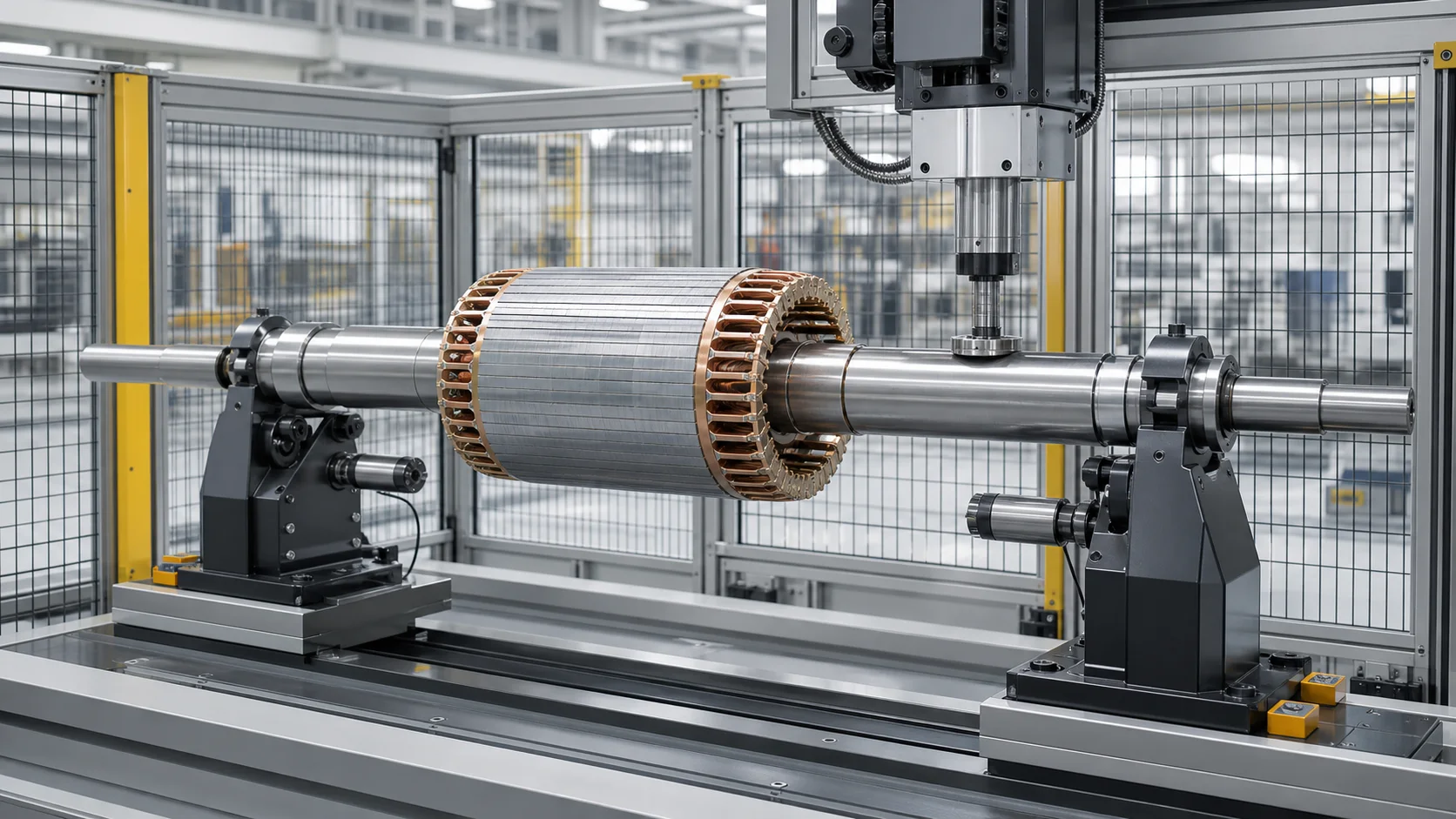
Dies ist eine Illustration eines technischen Konzepts, kein Foto vom Kundenstandort. Tatsächliche Rotorkonstruktion, Werkzeuge, Terminplan, Korrekturkraft und Automatisierungsgrad erfordern Zeichnungen und repräsentative Musterversuche.
Kompletter Rotor vs. nackte Motorwelle
Die erste Projektentscheidung ist, ob das Ziel eine Welle oder ein montierter Rotor ist.
| Werkstückzustand | Hauptfrage zur Geometrie | Dedizierter Prozessanliegen |
|---|---|---|
| Blanke Motorwelle | Ist die Wellenachse vor der Rotormontage akzeptabel?? | Zentren, Lagersitze, Keilnut/Gewinde/Keilnut und Verformung durch Wärmebehandlung |
| Welle mit Rotorpaket | Sind beide Lagerzapfen nach der Kern-/Käfig-/Magnetmontage ausgerichtet?? | Schutz des Rotorpakets, zusätzliche Steifigkeit, montagebedingte Biege- und Gleichgewichtssequenz |
| Rotor nach dem Fertigdrehen | Sind Lagerzapfen und Rotoraußendurchmesser im endgültigen Bezugszustand korreliert?? | Fertiger Oberflächenschutz und minimal zulässige Korrektur |
| Kompletter Motor | Ist der zusammengebaute Motor Vibrationen ausgesetzt?, Lärm, Strom- und Temperaturanforderungen? | Systemtest; keine Richtmaschinenabnahme an sich |
Bestehende Bare-Shaft-Anforderungen gehören dazu Automatische Lösung zum Richten von Motorwellen. Diese Seite gilt für den zusammengebauten Rotor oder Anker vor dem Einbau in das Stator- und Motorgehäuse.
Definieren Sie die Rotorfamilie
Unter dem Begriff „Motorrotor“ werden ganz unterschiedliche Werkstücke zusammengefasst. Der Vorschlag sollte identifizieren:
- Kurzschlussläufer-Induktionsrotor mit gegossenen oder gefertigten Endringen;
- gewickelter Rotor oder elektrischer Anker;
- Permanentmagnet- oder Synchronrotor;
- Rotor des Fahrmotors;
- Generatorrotor;
- Rotor mit Kommutator, Schleifringe, Lüfter, Encoderspur oder Kopplungsfunktion;
- Vollwelle, Hohlwelle oder Kühlkanal;
- ein Stück, gedrückt, eingeschrumpft, geschweißtes oder anderweitig zusammengebautes Rotorpaket;
- weich bearbeitet, wärmebehandelt, Fertiggeschliffen, beschichteter oder ausgeglichener Zustand;
- Rotor mit freiliegenden Korrekturspannen im Vergleich zu einem Design ohne sichere freiliegende Wellenzone.
Nicht jeder Rotor kann nach der Montage druckgerichtet werden. Permanentmagnete, Haltehülsen, Wicklungen, Isolierung, Hartlötverbindungen und Schnittstellen mit hoher Interferenz können starke Kräfte erzeugen, Temperatur- und Magnethandhabungsgrenzen. Für den tatsächlichen Bau muss die Machbarkeit nachgewiesen werden.
Frieren Sie die Herstellungsphase ein
Welle vor Rotormontage
Dies ist ein Projekt mit blankem Schaft. Der Korrekturzugriff ist normalerweise am besten, es kann jedoch die durch die spätere Presspassung verursachte Verzerrung nicht beseitigen, Schrumpfprozess, Druckguss oder Rotorpaketmontage.
Nach der Montage des Rotorpakets, Vor dem Fertigdrehen
Der komplette Montageeffekt ist vorhanden, Während der Bearbeitung kann Material auf den Lagerzapfen oder dem Rotoraußendurchmesser verbleiben. Galdabini beschreibt das Richten des Rotors als eine Möglichkeit, die Lagersitzgeometrie vor dem Drehen zu verbessern und unnötigen Materialabtrag zu reduzieren. Dies ist ein Prozessplanungsprinzip, keine universelle Materialeinspargarantie.
Nach dem Fertigdrehen oder Schleifen
Die Lagerzapfen, Schultern und Rotoroberfläche sind fertig. Werkzeugkontakt- und Eindruckgrenzen werden kritisch, Für die Korrektur dürfen nur zugelassene freiliegende Schachtspannweiten verwendet werden.
Nach dem Ausbalancieren
Durch das Richten kann sich die Rotorachse verändern, Massenverteilung relativ zu den Lagerzapfen und zuvor gemessene Unwucht. Ein nach dem Auswuchten korrigierter Rotor muss zur definierten Auswuchtprüfungsroute zurückkehren.
| Bühne | Vorteil | Hauptrisiko | Erforderliche erneute Überprüfung |
|---|---|---|---|
| Blanker Schaft | Maximaler Korrekturzugriff | Bei einer späteren Rotormontage kann es wieder zu einer Biegung kommen | Nach der Montage erneut messen |
| Rotor montiert, Lagerbestand bleibt bestehen | Montagebedingte Biegung ist sichtbar | Rotorpaket und Endelemente müssen geschützt werden | Zusammenhang zwischen Fertigbearbeitung und Bearbeitung |
| Fertigbearbeiteter Rotor | Funktionale Daten sind verfügbar | Oberflächenschäden und begrenzte sichere Presszonen | Vollständige Geometrie- und Oberflächeninspektion |
| Zuvor ausgewuchteter Rotor | Vorhandene Bilanzdaten sind verfügbar | Durch das Richten kann es ungültig werden | Endgültige Überprüfung des Kontostands |
Definieren Sie, was die Zeichnung steuert
„Rotorrundlauf“ sollte nicht als ein ungeteilter Wert behandelt werden. Relevante Merkmale können sein::
- Radialschlag jedes Lagerzapfens;
- koaxiale Beziehung zwischen den beiden Lagerzapfenachsen;
- Unrundheit der Wellenverlängerungen, Siegelspuren, Kupplungssitze oder Geberspuren;
- Rundlauffehler des Rotorkern-Außendurchmessers relativ zur Lagerachse;
- Kommutator- oder Schleifringschlag;
- Unrundheit der Schulterfläche;
- Geradheit einer freigelegten Schachtstrecke;
- Rundheit und Zylindrizität jedes Journals;
- axiale Position des Rotorpakets, Stapelzustand und Endringintegrität;
- statische und gekoppelte Unwucht in definierten Korrekturebenen;
- fertige Motorvibration, Lärm und elektrische Leistung.
Benutzen Sie die Wellengeradheit vs. Rundlauf vs. TIR-Führung Form trennen, abgeleitete Achsen- und Rotationsanzeige. Durch das Begradigen können globale Achsenbeziehungen verändert werden; Die Rundheit des Journals wird nicht automatisch korrigiert, Rotor-Stack-Geometrie, elektrische Defekte oder Massenunwucht.
Legen Sie das funktionale Datum fest
Für die meisten montierten Rotoren, Die beiden Lagerzapfen liegen zentral zur eingebauten Drehachse. Die SKF-Lagerführung für Elektromotoren behandelt Wellenlagersitze und Anlageschultern als kontrollierte geometrische Merkmale und berücksichtigt ausdrücklich Radial- und Planlauffehler. Das Projekt muss weiterhin der Kundenzeichnung und dem ausgewählten Lagersystem entsprechen.
Die Lösung sollte unterscheiden:
- Zeichnungsbezüge und funktionelle Lagerachse;
- Fertigungszentren zum Drehen oder Schleifen;
- Richtmaschinenständer und Drehvorrichtungen;
- Sensorspuren zur Rekonstruktion des Rundlauffehlers von Zapfen und Rotorkörper;
- Auswuchtmaschinenstützen und Korrekturebenen;
- Endmontage und Testreferenzen für den Motor.
Zentren können für die Bearbeitung nützlich sein, Eine durch den Mittelpunkt definierte Achse ist jedoch nicht automatisch dieselbe wie die Achse, die durch die fertigen Lagerzapfen festgelegt wird. Ebenfalls, Die wiederholte Abstützung eines Rotors beweist nicht, dass die Abstützungen den Lagerzustand des Kunden reproduzieren.

Diese technische Konzeptillustration zeigt mehrere Messspuren. Es sind keine Kontaktsensoren am Rotorpaket oder eine universelle Trägeranordnung vorgeschrieben.
| Messstrecke | Hauptausgang | Interpretationsrisiko |
|---|---|---|
| Lagerzapfen | Funktioneller Rundlauf der Rotationsachse und des Zapfens | Lokale Rundheit, Verschmutzung oder Sondenkraft können das Ergebnis verfälschen |
| Schaftverlängerungen | Biegen Sie die Lager nach außen | Keilnuten, Gewinde und Splines erzeugen ein falsches Signal |
| Außendurchmesser des Rotorkerns | Kern-Journal-Beziehung | Laminierungsschritte, Schlitze und absichtliche Oberflächenmerkmale müssen maskiert werden |
| Kommutator oder Schleifringe | Funktionsauslauf | Zerbrechliche Oberflächen erfordern möglicherweise eine berührungslose Erfassung |
| Schultern und Gesichter | Axial Runout | Fasen und Kantenbeschädigungen müssen ausgeschlossen sein |
| Referenzmarke der Waage | Winkelkorrelation | Eine Markierung kennzeichnet den Winkel, keine geometrische Konformität |
Trennen Sie das Rotorkernsignal von der Wellenbiegung
Eine laminierte Rotoroberfläche ist nicht immer ein glatter zylindrischer Bezugspunkt. Spielautomaten, verzerren, Laminierungsschritte, gegossene Endringe, Ausgleichsschnitte, Klebstoff, Beschichtungen und lokale Oberflächenvariationen können in einer Sensorspur auftreten.
Der Algorithmus sollte:
- Identifizieren Sie den Rotortyp und den Winkelbezug;
- Maskenschlitze, Keilnuten, Threads, Löcher und Balance-Korrekturbereiche;
- Verwenden Sie mehrere Winkelpositionen, um wiederholbare Formen von globalen Biegungen zu trennen;
- Bewerten Sie beide Lagerzapfen und mindestens das zeichnungsrelevante Rotormerkmal;
- Vermeiden Sie die Umwandlung eines lokalen Laminierungs- oder Endringsignals in einen starken Druckbefehl;
- Vergleichen Sie das freigegebene Ergebnis gegebenenfalls mit einem unabhängigen Messgerät oder einer Auswuchthilfe.
Wenn der Rotoraußendurchmesser relativ zu den Lagerzapfen nach dem Richten fertiggedreht wird, Im Abnahmeplan muss angegeben werden, welche Geometrie als Zwischen- und welche als Endgeometrie gilt.
Schützen Sie das Rotorpaket und die elektrischen Komponenten
Das Rotorpaket sollte normalerweise als verbotener Korrekturkontakt behandelt werden, es sei denn, der Designinhaber genehmigt ausdrücklich eine spezielle Vorrichtung.
Typische No-Press- und No-Support-Zonen
- Blechpaket- und Rotorschlitze;
- Käfigläuferstangen und Endringe;
- Permanentmagnete und Haltehülsen;
- Wicklungen, Isolierung und Banderolierung;
- Kommutator und Schleifringe;
- Fans, Encoder und Sensorspuren;
- Lagerzapfen, Dichtungsspuren und fertige Presspassungen;
- Schultern, Verrundungen und Abschnittsübergänge;
- Keilnuten, Splines, Threads, Querbohrungen und Kühlkanäle;
- Schweißnähte, Hartlötverbindungen und lokal gehärtete Zonen.
Grundsätze des sicheren Lastpfads
- Nur bei zeichnungsgeprüften freiliegenden Schachtspannweiten korrekt;
- Verwenden Sie Schuhe und Stützen mit großem Radius, die auf den Wellendurchmesser abgestimmt sind;
- Halten Sie den Rotorstapel außerhalb des direkten Lastpfads der Presse;
- Verhindern Sie Kantenbelastungen in Schulternähe und passen Sie Übergänge an;
- Überwachen Sie Kraft und Weg über den gesamten Hub;
- Stoppen Sie bei ungewöhnlicher Steifheit, Schlupf oder Sensorverhalten;
- Begrenzen Sie die Anzahl der Korrekturen und die akkumulierte plastische Dehnung;
- Lassen Sie es vollständig los, bevor Sie das Ergebnis auswerten.
Bei manchen Kompaktrotoren fehlt die freiliegende Wellenspannweite für eine sichere Dreipunktkorrektur. Die richtige Entscheidung könnte darin bestehen, den blanken Schaft früher zu begradigen, Ändern Sie die Montageroute, Verwenden Sie ein anderes Korrekturkonzept oder lehnen Sie die Baugruppe ab.
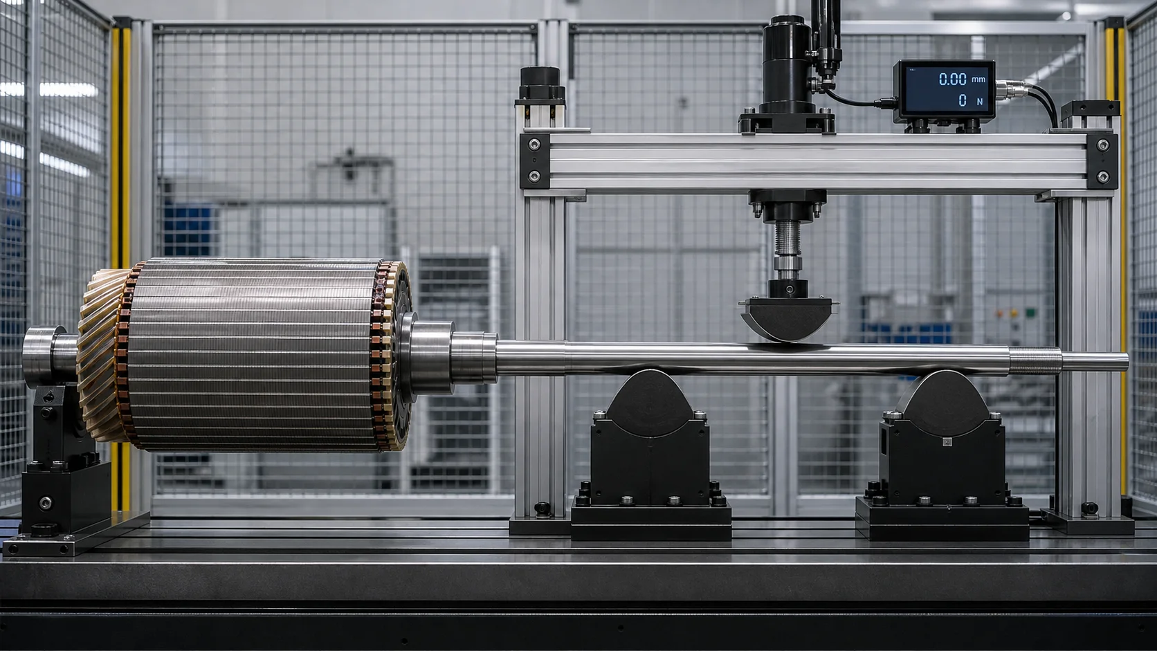
Diese Konzeptdarstellung hält das Rotorpaket bewusst außerhalb des Pressenrahmens und übt die Dreipunktlast nur auf einen freiliegenden Wellenbereich aus. Tatsächliche Unterstützungskoordinaten, Schuhradius und Kraftgrenzen erfordern repräsentative Muster.
Geradheit und Ausgewogenheit sind unterschiedlich
Aufrichten und Balancieren lösen unterschiedliche körperliche Probleme.
| Zustand | Geometriemessung | Auswuchtmessung | Richtige Antwort |
|---|---|---|---|
| Gebogene Schaftachse | Erkennt die Beziehung zwischen Zapfen, Welle und Kernrundlauf | Kann als geschwindigkeitsabhängiges Vibrations- oder Unwuchtsignal auftreten | Korrekte Geometrie, wenn der Rotor innerhalb des genehmigten Bereichs liegt |
| Massenunwucht bei geraden Zapfen | Geometrie kann passieren | Erkennt Größe und Winkelposition in einer oder mehreren Ebenen | Masse mit der zugelassenen Auswuchtmethode entfernen/hinzufügen |
| Fehler im lokalen Journalformular | Erkennt Rundheits-/Zylindrizitätsprobleme | Kann das Unterstützungsverhalten stören | Maschine oder Ausschuss; Nicht als globale Biegung behandeln |
| Exzentrizität des Rotorkerns gegenüber den Lagerzapfen | Der Rundlauf des Kerns unterscheidet sich von der der Zapfenachse | Kann zu Ungleichgewichten und elektromagnetischen Effekten beitragen | Bestimmen Sie, ob Geometrie, Bearbeitung oder Montage ist verantwortlich |
| Thermobogen | Die Kaltgeometrie kann vom Betriebszustand abweichen | Kann sich je nach Geschwindigkeit und Temperatur ändern | Erfordert Wärme-/Betriebszustandstechnik, keine blinde Kältekorrektur |
Die Auswuchtführung von Schenck unterstützt Rotoren auf ihren eigenen Zapfen und misst die Unwucht in definierten Ebenen. Das ist ein anderer Vorgang als die Rekonstruktion einer gebogenen Achse und die Anwendung einer Presskorrektur. Durch das Auswuchten wird ein verbogener Rotor nicht gerade, während das Richten einen Rotor nicht ausbalanciert.
Empfohlene Reihenfolge
- Legen Sie die Montagestufe und den Bezugspunkt des Funktionsjournals fest;
- Freigegebene Geometrie messen;
- Richten Sie das Gerät nur innerhalb der zugelassenen Zonen und Materialgrenzen;
- Nach der Freigabe die gesamte Geometrie erneut messen;
- Komplette Endbearbeitung, wo geplant;
- Führen Sie das Auswuchten in den erforderlichen Ebenen durch oder überprüfen Sie es;
- Komplette abschließende Rotor- und Motortests.
Wenn Produktionsbeschränkungen eine andere Bestellung erfordern, Der Validierungsplan muss zeigen, wie sich spätere Operationen sowohl auf die Geometrie als auch auf das Gleichgewicht auswirken.
Kontrollunterstützungseinfluss und freigegebene Messung
Rotormasse, Stützabstand und Zapfenzustand beeinflussen die beobachtete Kurve. Die Zelle sollte definieren:
- exakte Zapfenauflagepositionen und Rollenprofil;
- Rotorausrichtung und Winkelindexierungssequenz;
- Anpressdruck und Oberflächenschutz;
- Sensorkraft oder berührungsloser Abstandshalter;
- Durchhangbehandlung für lange oder schwere Rotoren;
- Temperaturstabilisierung;
- geladener versus losgelassener Messzustand;
- Zusammenhang mit der Auswuchtmaschine und der endgültigen Motorlehre.
Schenck dokumentiert das Auswuchten von Rotoren auf eigenen Wellenzapfen mittels Rollen- oder anderen anwendungsspezifischen Lagerungen. Das übertragbare Prinzip besteht darin, dass die Stützbedingung Teil der Messdefinition ist; Die Konstruktions- und Leistungsangaben der Auswuchtmaschine stellen keine Leistungsansprüche von StraighteningTech dar.
Rotorrichtprozess mit geschlossenem Regelkreis
1. Identifizieren Sie den Rotor
Wählen Sie das validierte Rezept aus der Teilenummer aus, Rotorkonstruktion, Montagephase, Materialzustand und Zeichnungsüberarbeitung.
2. Inspizieren und reinigen
Überprüfen Sie Zeitschriften, Keilnuten, Endringe, Laminierungen, Magnete/Hüllen, Kommutator, Saldokürzungen und andere Ablehnungsbedingungen. Reinigen Sie die zugelassenen Auflage- und Messschienen.
3. Laden Sie auf genehmigte Journale oder Prozessdaten
Bestätigen Sie die Rotorausrichtung, Sitz- und Winkelbezug, ohne fertige Oberflächen zu ziehen.
4. Alle kontrollierten Spuren messen
Drehen Sie den Rotor und rekonstruieren Sie die Lager-Zapfen-Achse, freiliegende Wellenkurve und zeichnungsrelevante Rotor-Körper-Beziehung. Diskontinuitäten maskieren.
5. Klassifizieren Sie die Abweichung
Trennen Sie korrigierbare globale Biegungen von lokalen Formfehlern, lose Montage, Exzentrizität des Rotorpakets, elektrischer Schaden oder Massenunwucht.
6. Wählen Sie eine sichere Korrekturspanne
Benutzen Sie nur zugelassene freiliegende Schachtbereiche. Bestätigen Sie die Supportspanne, Korrekturrichtung, Kraft-/Weggrenzen und Rotor-Stapel-Abstand.
7. Wenden Sie eine kontrollierte Korrektur an
Verwenden Sie das validierte Rückfederungsmodell, Überwachen Sie Kraft und Verschiebung und stoppen Sie bei abnormalen Signaturen.
8. Vollständig loslassen und erneut messen
Beurteilen Sie den unbeladenen Rotor. Überprüfen Sie die Zeitschriften erneut, Wellenverlängerungen und Rotor-Körper-Spuren, da eine Korrektur mehrere Beziehungen verschieben kann.
9. Inspizieren und weiterleiten
Führen Sie die erforderliche Oberfläche aus, Riss, Elektro- und Montageprüfungen. Leiten Sie konforme Rotoren zur Endbearbeitung oder zum Auswuchten; Leiten Sie abnormale Teile zur technischen Überprüfung weiter.
10. Notieren Sie das Ergebnis
Rotoridentität speichern, Rezeptüberarbeitung, Vorher/Nachher-Karten, Korrekturkoordinaten, Kraft-Weg-Kurven, Alarme und Disposition, wenn Rückverfolgbarkeit erforderlich ist.
Vorgeschlagene Zellkonfiguration
Eine projektspezifische Rotorzelle kann umfassen:
- elektromechanische oder hydraulische Presse, ausgewählt aus Beispielkraftdaten;
- geschützte Zapfenrollen, Zentren oder kundenspezifische Rotationsvorrichtungen;
- Kontakt- oder berührungslose Sensoren für Zeitschriften, Wellenverlängerungen und Rotorkörper;
- Winkelindizierung und Merkmalsmaskierung;
- austauschbare Werkzeuge mit großem Radius und fehlersicherer Einrichtung;
- bewachte automatische oder bedienergestützte Beladung;
- Gewalt, Verdrängungs- und Rezeptsteuerung;
- Nachmessung im freigegebenen Zustand;
- Teileidentifikation und Rückverfolgbarkeit;
- Schnittstellen zur Fertigbearbeitung, Auswucht- und Qualitätssysteme.
Galdabini listet Handbuch auf, Kette/Gabel, Portal- und Roboterbeladungskonzepte für Elektrorotoren. Der endgültige Automatisierungsgrad sollte der tatsächlichen Rotormasse folgen, Variantenanzahl, Oberflächenempfindlichkeit und Produktionsfluss.
Musterprüfung und Abnahme
Die repräsentative Probenmatrix sollte abdecken:
- kleinste und größte Wellen- und Rotorkerndurchmesser;
- minimale und maximale Rotorlänge und -masse;
- jede Rotorkonstruktion und Montagemethode;
- Gegebenenfalls Voll- und Hohlwellen;
- Material- und Wärmebehandlungszustände;
- minimale und maximale eingehende Biegung;
- alle exponierten Korrekturspannen und Sperrzonen;
- Lagerzapfen vor und nach der Fertigbearbeitung;
- Rotorkern, Kommutator, Schleifring- oder Encoderfunktionen;
- zuvor ausgeglichene und unausgeglichene Proben;
- Korrelation zwischen Kundenmaß und Auswuchtmaschine;
- Oberfläche, Riss, Elektro- und Montageprüfung nach der Korrektur.
Benutzen Sie die Test- und Abnahmeleitfaden für Richtproben Machbarkeit zu trennen, FETT, SAT- und Produktionsfähigkeit. Ein Maschinenkatalogwert ist kein Hinweis auf eine bestimmte Rotorfamilie.
Für ein technisches Angebot erforderliche Daten
Bitte angeben:
- Rotorbaugruppe und Wellenzeichnungen;
- Rotortyp, Montagemethode und Herstellungsweg;
- Material, Wärmebehandlung, Härte und Oberflächenbeschaffenheit;
- Teilevarianten, Masse, Länge und Rotorkerndurchmesser;
- Richtstufe relativ zur Montage, Bearbeitung und Auswuchten;
- Zeichnungsbezüge und kontrollierte Rundlauf-/Geradheitseigenschaften;
- eingehende Abweichungsverteilung und bekannte Baugruppenverzerrung;
- genehmigte Support- und Pressebereiche;
- geschützte Laminierungen, Ringe, Magnete, Wicklungen, Keilnuten und Fertigpassungen;
- Korrekturanzahl, Riss, elektrische und Oberflächengrenzwerte;
- Ausgleichsflugzeuge, Methode und erforderliche Nachprüfung;
- Anforderungen des Kundenmaßes und der abschließenden Motorprüfung;
- Automatisierung, Rückverfolgbarkeits- und Berichtsanforderungen;
- repräsentative Proben für Versuche.
Häufig gestellte Fragen
Kann die Presse die Rotorlamellen anschieben??
Gehen Sie nicht davon aus. Laminierungen, Käfigstangen, Endringe, Magnete und Wicklungen sind funktionsfähig und schadensanfällig. Das Standardkonzept hält sie außerhalb des Korrekturlastpfads, es sei denn, der Rotorkonstrukteur genehmigt eine spezielle Vorrichtung und Validierung.
Sollten wir uns vor oder nach dem Ausbalancieren aufrichten??
Die Geometrie sollte normalerweise vor dem endgültigen Auswuchten festgelegt werden. Wenn ein Rotor nach dem Auswuchten gerade gerichtet wird, Der Gleichgewichtszustand muss erneut überprüft werden, da sich die Beziehung zwischen Rotationsachse und Masse möglicherweise geändert hat.
Kann eine Zelle blanke Wellen und komplette Rotoren verarbeiten??
Möglicherweise, aber nur mit separaten Rezepten, unterstützt, Sensorspuren, Werkzeugkarten und Validierung. Der komplette Rotor fügt Masse hinzu, Steifheit, fragile Merkmale und Balance-Verantwortung.
Beweist eine geringe Vibration, dass der Rotor gerade ist??
NEIN. Vibration hängt vom Gleichgewicht ab, Lager, Stützstruktur, elektromagnetische Kräfte, Ausrichtung, Geschwindigkeit und Temperatur. Freigegebene Geometrie muss direkt an der Zeichnungsvorgabe gemessen werden.
Kann die Genauigkeit anhand eines CAD-Modells garantiert werden??
NEIN. CAD definiert Geometrie, aber reale Proben bewirken eine materielle Reaktion, montagebedingte Biegung, unterstützenden Einfluss, Rückfederung, Oberflächenrisiko und ausgleichende Korrelation.
Bauen Sie die Lösung rund um den kompletten Rotor auf
Wir entwickeln Lösungen zum Richten von Rotoren von Elektromotoren rund um die eigentliche Montagephase, Lagerzapfendatum, geschütztes Rotorpaket, sichere exponierte Schachtbereiche, freigegebene Geometrie und endgültige Auswuchtroute. Die Ausrüstung kann manuell sein, halbautomatisch oder vollautomatisch, Die Korrekturlogik muss jedoch spezifisch für die Rotorfamilie bleiben.
Sobald die Fragen zum Rotorprozess des Elektromotors beantwortet sind, Zwei Seiten verkürzen in der Regel die Shortlist: Die Komplettlösung zur Auswahl eines Glätteisens und die Budgetbild für eine Richtmaschine.
Senden Sie die Rotor- und Wellenzeichnungen, Montageweg, eingehende Rundlaufdaten, Karte mit geschützten Merkmalen und Ausgleichsmethode. Anschließend können wir den Messplan definieren, Werkzeuge, Korrekturumschlag, Mustermatrix und nachvollziehbarer Abnahmeprozess für Ihren Elektromotorrotor.