
Flere forskydningsaflæsninger kan forvandle en langskaftet inspektion fra en enkelt top til et fejlkort. Denne værdi afhænger af mere end sensoren: støtte geometri, datum siddeplads, sondekontakt, rotation/indeksering, synkronisering, miljøforhold og regnereglen har alle indflydelse på, hvad der indberettes.

*Engineering koncept illustration. Det er ikke en sensorspecifikation, installeret system eller verificeret måleresultat.*
Definer karakteristikken, før du vælger sensorer
Angiv først, om acceptkarakteristikken er midterliniens rethed, lokal bue, runout i forhold til et datum, profilafvigelse eller et andet kontrolleret resultat. En sensorspændings- eller forskydningssporing er ikke i sig selv kundens krav. Inspektionsplanen skal identificere datumfunktioner, støtter, stationer, orienteringer, span, beregning, enheder, grænser og den tilstand, hvor delen er accepteret.
| Element | Spørgsmål at lukke |
|---|---|
| Datum | Hvilke funktioner etablerer referenceaksen eller overfladen? |
| Støtte | Replikerer det kundens eller frigivne dels tilstand? |
| Probe sti | Er kontaktpunkter funktionelle overflader og beskyttet mod skader? |
| Stationer | Fanger de kendte bøjningszoner og har overgange? |
| Rotation/indeksering | Hvordan bevares orienteringen mellem læsningerne? |
| Beregning | Hvordan konverteres aflæsninger til den kontrollerede karakteristik? |
Til datum kontrol, se rensning af akslens midterhul og klargøring af datum og armaturets repeterbarhed og datum-sæde.
Sådan fungerer en LVDT, og hvorfor dens fysik betyder noget
Den lineære variable differentialtransformator tjener sin plads på produktionsmaskineri gennem en kort liste over fysiske dyder. Inde i huset, en primær spole exciteres med en vekselstrøm, og to sekundære spoler sidder på hver side af den; en ferromagnetisk kerne, fastgjort til sondespidsen med en slank skubbestang, glider langs aksen. Med kernen centreret, de inducerede spændinger i de to sekundære balancer; forskyd kernen og balancespidserne i forhold til bevægelsen. Elektronikken aflæser amplituden og fasen af den ubalance og rapporterer forskydning. Fordi kernen aldrig rører spolerne, der er ingen friktion eller slid inde i sensoren; fordi koblingen er induktiv, læsningen er stort set ligeglad med støv, olietåge og fugt, der blinder optiske sensorer; og fordi den bevægelige masse er lille, spidsen kan følge moderat overfladebevægelse trofast. Afvejningerne er lige så fysiske: den har brug for signalbehandling og kalibrering mod en reference, det rå output er relativt snarere end absolut, og selve sondespidsen er en mekanisk komponent med sin egen tilstand, kraft og slid historie.
Hvor fejl indtastes mellem sonde og nummer
Behandling af kæden som ét system, som afsnittet ovenfor kræver, betyder at kende de specifikke døre, hvorigennem fejlen kommer ind. Termisk drift: sensorlegemet, armaturet og delen udvider sig og trækker sig sammen med temperaturen, og på en maskine, der varmer gennem et skift, en morgen nul og en eftermiddagsmåling er ikke den samme hændelse — derfor referencetjek på en master med intervaller, som proceduren definerer. Montering: en sonde på en lang, ikke-understøttet beslag er en cantilever med sin egen overensstemmelse, og vibration eller kabeltræk bevæger hele samlingen i forhold til delen, ikke kan skelnes fra delbevægelser i dataene. Dynamik: når delen eller sonden bevæger sig under scanning, pennens masse og spidskraft sætter en hastighedsgrænse, ud over hvilken spidsen springer eller halter, skrive falske træk ind i sporet. Kontakttilstand: spidsslitage udjævner den tilsigtede radius og ændrer sig, hvor aflæsningen sidder på en buet overflade. Ingen af disse er eksotiske; hver styres af skriftlig procedure — nul metode, master check interval, scanningshastighed, tipinspektion — hvilket netop er det, som ovenstående valideringsramme beder systembeskrivelsen om at indeholde.
Behandl målekæden som ét system
En LVDT kan være egnet til relativ forskydning, men det målte resultat inkluderer også sensormontering, armaturafbøjning, signalkonditionering, timing, delsæde og operatør- eller automatiseringsadfærd. Registrer hvert element i kæden, så et senere skift i resultatet kan undersøges.
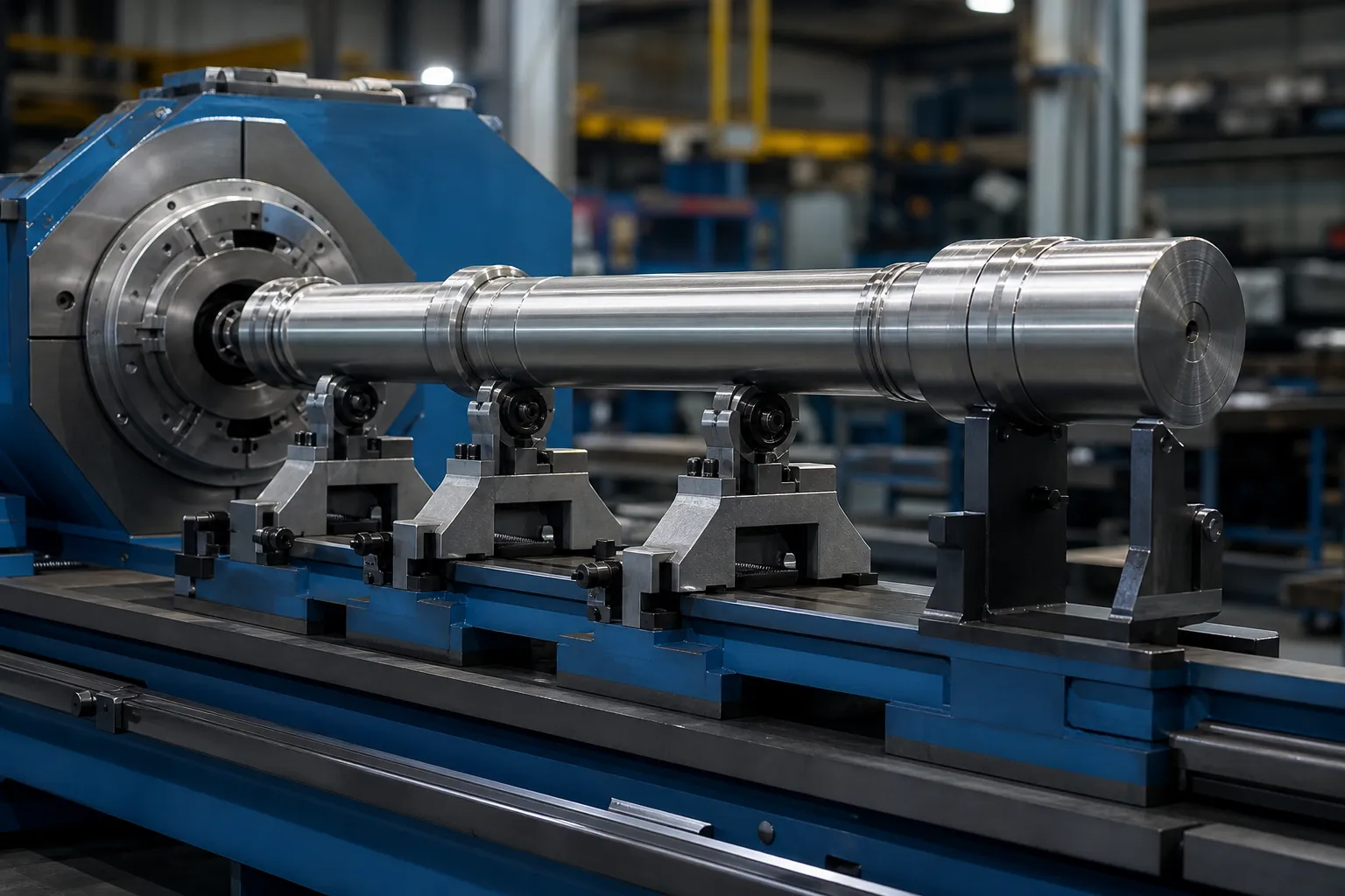
*Engineering koncept illustration. Fixturstivhed, sensorposition og afskærmning kræver projektspecifik konstruktion.*
Den kontrollerede procedure bør dække sensoridentifikation, reference/mastercheck, monteringstilstand, kabelbeskyttelse, nul metode, prøve orientering, understøtte renlighed, dataindsamlingsindstillinger og dataopbevaring. En gentagen aflæsning fra et ustabilt armatur er ikke bevis for repeterbarhed.
Synkroniser placering, Orientering og oplæsning
Multipoint-data er kun nyttige, når hver værdi kan tildeles en kendt position og tilstand. Hvis delen roterer eller bevæger sig, definere encoderen/indekset, stationskoordinat, kørselsretning, opholds- eller prøveudtagningstilstand, og hvad sker der, hvis der mangler et signal. Resultatet skal bevare de rå eller sporbare kildedata, der er nødvendige for at rekonstruere kortet.
Undgå at fortolke en lokaliseret top uden at kontrollere siddepladser og kontakt. Gentag prøver, omvendt orientering, hvor det er passende, og gentagne basislinjelæsninger kan skelne en delfunktion fra en falsk indikation.
Valg af stationstal og placering
Hvor mange stationer, og hvor, er et geometrispørgsmål før det er et budgetspørgsmål. Fejltilstandene for slanke dele er glatte i rummet: et bøjning er en lavfrekvent kurve, så et beskedent antal stationer - placeret hvor fysikken siger, at informationen lever - rekonstruerer det godt, mens fordobling af antallet i uinformative positioner køber datavolumen, ikke nøjagtighed. Informative positioner er forudsigelige: midt mellem støtterne, hvor en bue når sin udflugt; hver stivhedsovergang på trindelte dele, hvor tinder gerne gemmer sig; umiddelbart ved siden af funktionelle træk, hvis forhold til datumet har betydning; og de frie ender, som forankrer kortet. Fejltilstanden for sparsom placering er aliasing i sin praktiske form - et kort knæk mellem to stationer bidrager til hverken at læse rent, og en rettelse rettet mod de rekonstruerede kort trykker det forkerte sted. Den ærlige måde at lukke denne risiko på er ikke uendelig tæthed, men en validering: kortlæg et sæt dele med høj tæthed én gang, bekræfte, at produktionsstationssættet rekonstruerer de samme toppe og amplituder, og dokumentere den sammenligning som stationsplanens begrundelse.
Forvandling af kortet til en rettelsesbeslutning
Kortet er til for at drive handling, og dets handlingsordforråd har tre poster: hvor man skal trykke, i hvilken retning, og hvor svært det er at forvente, at delen svarer. Topposition og retning kommer fra sammenligning af stationer omkring maksimum; på en del, der roterer mellem stationerne, bevarelse af vinkelindeksering - synkroniseringsdisciplinen ovenfor - er det, der konverterer separate aflæsninger til en vektor, ikke en bunke størrelser. Forventet respons kommer fra den stivhedshistorie, som kortet allerede fortæller: en top på en tung sektion har brug for en anden korrektionsplan end den samme amplitude på en tynd, og toppe ved stivhedsovergange fortjener respekten beskrevet for adskiller bøjning fra rundhed og opsætningseffekter før nogen presse følger. Hvad kortet ikke må, er at udløse korrektion på ikke-verificerede signaler: en lokaliseret aflæsning, der ikke har overlevet en gensædekontrol, er en hypotese, ikke et højdepunkt. Det rækværk — kort, verificere, derefter rette, med frigivet tilstandsmåling, der lukker løkken — er den samme sekvens, der gør automatisk akselretning konvergere i få slag i stedet for mange.
Korreler med Accept af frigivet del
Måling under fastspænding eller korrektion kan være nyttig til processtyring, men det beviser ikke automatisk, at den frigjorte aksel opfylder kravet. Sammenlign linjemetoden med en godkendt frigivet del-metode på repræsentative prøver på tværs af normal variation. Se måling af belastet versus frigivet rethed for grænsen.
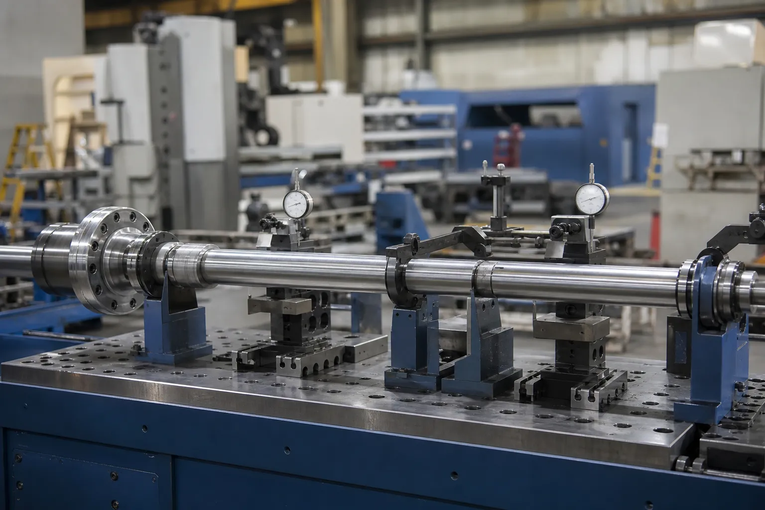
*Engineering koncept illustration. Referencemetoden, understøtninger og acceptberegning skal kontrolleres af den godkendte kvalitetsplan.*
En korrelationsplan bør definere matchede prøver, blind sammenligning, hvor det er praktisk, datum/støtte ækvivalens, kalibreringsstatus, bias anmeldelse, gennemgang af repeterbarhed/reproducerbarhed, tilladt forskel, eskalering og ændringskontrolregler. Der henvises til maskinmåler versus kundemåler korrelation og gage R&R for at rette linjer.
Nødvendige input til en måleundersøgelse
Giv tegningen og karakteristisk definition, eksisterende kontrolmetode, delgeometri og datumfunktioner, materiale/fremstillingsfase, forventede bøjningssteder, prøvepopulation, miljømæssige begrænsninger, ønsket dataregistrering og kundeacceptmetode. Brug udretning prøve test og accept guide for at etablere forsøgsjournalen, så kontakt StraighteningTech til en ansøgningssamtale.
Nødvendig validering før et systemkrav
Enhver flerpunktsmåling kræver en defineret sonde- og datumopsætning, kalibrerede referencer, gentagne eller genplacerede aflæsninger på repræsentative dele, og kundemåler korrelation. En generisk maskinkapacitet er ikke et verificeret resultat.
FAQ
Forbedrer tilføjelse af flere målestationer automatisk nøjagtigheden?
Ingen. Stationer, der er placeret, hvor geometrien har information - toppe i midten af spændvidden, stivhedsovergange, funktionelle funktioner, slutter — forbedre kortet. Stationer tilføjet andre steder tilføjer datavolumen og omkostninger, mens rekonstruktionen i det væsentlige forbliver uændret. Valider det valgte sæt én gang mod et tæt kort og dokumenter sammenligningen.
Hvorfor glider LVDT-aflæsninger over et produktionsskift?
Oftest termisk: sensor, armaturet og delen udvider sig med forskellige hastigheder, når cellen opvarmes, at skifte nul. Mekaniske årsager kommer dernæst - overholdelse af beslag, kabeltræk, spidsslid. Kontrollen er proceduremæssig: en defineret nul-metode og reference-master-tjek med faste intervaller, med ethvert skift ud over procedurens grænse, der udløser undersøgelse snarere end stille nulstilling.
Kan multipoint LVDT-data erstatte slutinspektion?
Kun gennem korrelation. Multipoint-data i processen driver korrektionsløkken; acceptbeslutningen tilhører den frigivne tilstandsmetode, som kunden genkender. Når de to har en dokumenteret sammenhæng på repræsentative dele, linjemetoden vinder stående — indtil da er det processtyring, ikke frigive.
Relaterede StraighteningTech-ressourcer
Se hvordan automatisk akselretning fungerer, udretning prøve test og accept og akslens rethed vs runout vs TIR for generiske kontrolgrænser, der gælder før ethvert kapacitetskrav på LVDT Multipoint akselmåling.
Flerpunktsmåling betaler sig på accepttidspunktet – parre FEDT tjekliste med GD&T rethed accept guide at aftale målemetode og tolerancefortolkning i én omgang.