
En krumtapaksel er en flerakset træthedskritisk komponent, ikke et konventionelt rundt skaft. Dens hovedlejetapper bør etablere en fælles rotationsakse, mens hver plejlstangs krumtap bevidst følger en forskudt bane. Webs, modvægte, stødflader, filet radier, oliehuller, næsetræk og svinghjulsflangen påvirker alle målingen og den sikre belastningsvej.
En pålidelig krumtapakselretningsløsning skal derfor besvare fem spørgsmål inden maskinvalget:
- Er dette en produktionskrumtapaksel, en genfremstillingsdel eller en reparation af små motorer?
- Hvilken hovedjournalakse og støttetilstand definerer bøjningskortet?
- Er afvigelsen en korrigerbar global bøjning, lokal journal formular fejl, slibemateriale problem eller revne/skade tilstand?
- Hvilket tryk, rulnings- eller gnidningsrute er godkendt til materiale- og processtadiet?
- Hvordan vil frigivet geometri, filetens integritet, slibegodtgørelse og slutbalance verificeres?
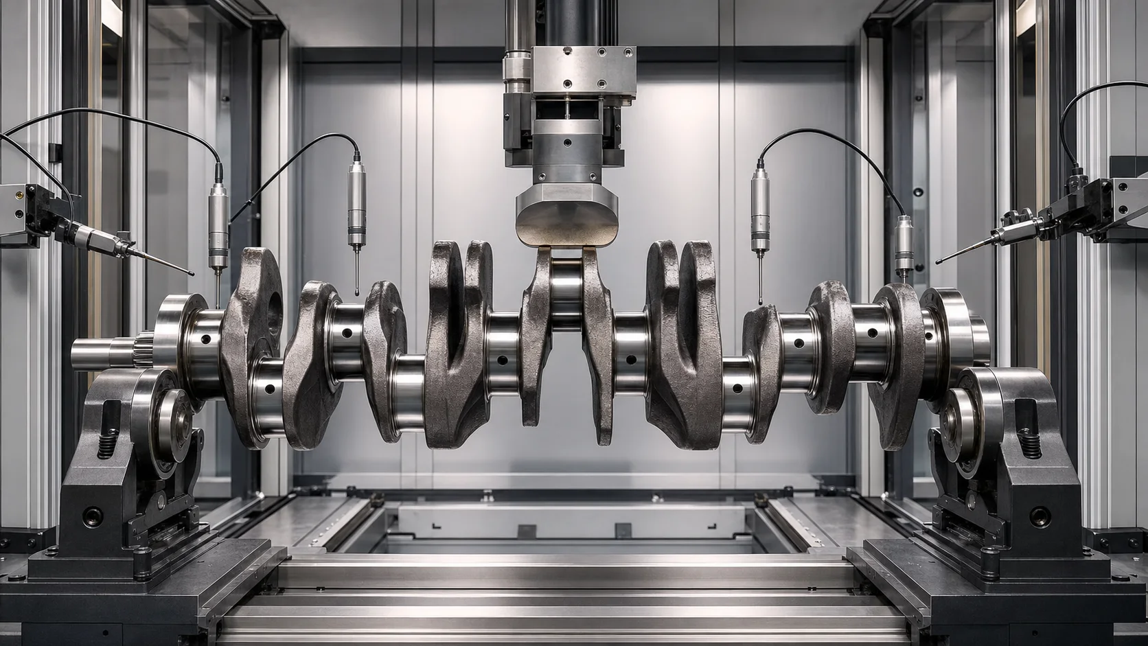
*Engineering koncept illustration: en multi-throw krumtapaksel understøttet og målt til en kontrolleret korrektionsundersøgelse. Det er ikke et fotografi fra kundens websted. Faktiske kontaktzoner, kraftgrænser og maskinarkitektur kræver tegninger og repræsentative prøveprøver.*
Krumtapakselretning er ikke ét marked
DataForSEO resultater for crankshaft straightening machine vise flere forskellige søgehensigter på den samme resultatside: reparationsværktøj til små motorer, værksted hydrauliske presser, stort krumtapakselreparationsudstyr og højproduktionssystemer til dybderulning/rulleudretning. Disse bør ikke kombineres i ét generisk maskintilbud.
| Krumtapaksel familie | Typisk kontekst | Ingeniørrute |
|---|---|---|
| Smedet bilkrumtapaksel | Kontrolleret produktion mellem bearbejdningsoperationer | Automatiseret måling plus valideret tryk- eller rulleudretningsproces |
| Stor diesel, marine eller industriel krumtapaksel | Ny produktion eller specialreparation | Tung håndtering, flere understøtninger og projektspecifik tryk/rulningsrute |
| Genfremstilling af krumtapaksel | Slid, varme, styrt- eller lejefejlshistorik | Inspektion, slibe- og reparationsbeslutning før udretning |
| Lille lodret aksel motorhåndsving | Kompakt reparationsværktøjsmarked | Separat produkt, armatur og sikkerhedskonvolut |
| Opbygget eller presset krumtapaksel | Flere samlede baner, stifter og interferenspasninger | Monteringsjusteringsproces; ikke en opskrift på smedet håndsving i ét stykke |
| Støbe- eller nodulær krumtapaksel | Materialespecifik træthed og revneadfærd | Metallurgisk godkendelse og begrænset korrektionsundersøgelse |
Denne side fokuserer på industri- og bilkrumtapaksler i ét stykke. Et lille glattejern eller en indbygget motorcykelkrumtapaksel har brug for en anden løsning.
Definer krumtapakslens anatomi og datumkæde
Det tekniske forslag bør identificere alle funktionelle funktioner:
- alle hovedlejejournaler og deres nummerering;
- plejlstangs krumtappinde, slagtilfælde og vinkelfase;
- baner og modvægte;
- forreste næse, timing, nøglespor, spline eller gearfunktioner;
- bageste flange, pilotboring og svinghjulsgrænseflade;
- trykflader og aksialt datum;
- vigtigste- og pin-journal filet radier;
- oliehuller, krydsboringer og indvendige passager;
- hærdede eller dybvalsede områder;
- balance huller, fræsede puder eller tilføjede balancefunktioner;
- centre eller midlertidige procesdatums;
- formalingsmateriale efter journal og procestrin.
Hovedjournalens fælles akse styrer normalt den globale bøjningsbeslutning. Krankpinde er bevidst excentriske og skal vurderes i forhold til hovedaksen, slagtilfælde og fase. En krumtappins rå radiale bevægelse er ikke direkte bevis på en bøjet aksel.
Frys produktions- eller reparationsfasen
Efter smedning og grovbearbejdning
Delen kan indeholde skala, lagervariation og ufærdige datumfunktioner. Korrektion kan understøtte downstream-bearbejdning, men målesystemet skal skelne lagervariation fra faktisk akseforskydning.
Efter Main- og Pin-Journal Pre-Machining
Funktionelle journalspor og procesdatum er tilgængelige, mens der er slibetilskud tilbage. Hegenscheidt beskriver dybvalsning og rulleudretning efter forbearbejdning, med hovedleje-TIR målt før korrektionsberegningen. Dette bekræfter, at processtadiet og lagerplanen er uadskillelige.
Efter varmebehandling eller overfladehærdning
Reststress, hårdhed og tilbagespring kan ændre sig. En kraft/forskydningsopskrift fra et blødt emne kan ikke automatisk overføres til en hærdet krumtapaksel. Revnerisiko og inspektion efter proces bliver eksplicitte acceptporte.
Efter Filet Deep Rolling
Dybvalsning bruges til at fremkalde restspænding ved højt belastede fileter. En efterfølgende korrektionsoperation må ikke ødelægge den tilsigtede filettilstand eller pålægge en uvalideret belastningsvej. Trykkontakt på fileten er forbudt, medmindre krumtapakseldesigneren godkender en dedikeret proces.
Før endelig slibning
Opretning kan reducere det materiale, der kræves for at generere en fælles hovedakselakse. Det udgående kort skal bevise, at enhver journal stadig har tilstrækkeligt slibetillæg.
Efter afsluttende slibning
Journal diameter, rundhed, overfladefinish, filetgeometri og trykflader er funktionelle. Kontakten bliver mere restriktiv, og en genslibnings-/reparations-/afvisningsrute kan være sikrere end yderligere trykkorrektion.
Service eller genfremstilling retur
Varmeskader, lejeanfald, scoring, revner, tidligere slibning, svejsning, plettering eller forudgående opretning kan ændre risikoen. En reparationshistorik og inspektionsjournal er påkrævet, før der påføres kraft.
| Scene | Hovedmulighed | Hovedrisiko | Påkrævet bevis |
|---|---|---|---|
| Groft smedning | Reducer bearbejdningsubalance | Lagervariation maskerer geometri | Kvalificerede procesdatums og lagerkort |
| Forbearbejdet | Multi-journal bøjningskort er tilgængeligt | Forkert supportreference | Hovedjournal TIR og slibetillæg |
| Varmebehandlet | Korrekt varmebehandlingsforvrængning | Tilbagespring og revneinitiering | Materiale/hårdhed og kraft-forskydningsforsøg |
| Dybvalset | Koordinere runout- og filetstyrkeproces | Beskadigelse af kompressiv filettilstand | Proces-ejergodkendelse og filetbeskyttelse |
| Afslut-slebet | Bjærgning inden for endelig geometri | Overflade/formskader og bortkommet lager | Fuld journal/filet inspektion og reparationsgrænse |
| Service retur | Gendan en komponent, der kan repareres | Skjult træthed, varme eller skader før reparation | NDT, historie, lager- og dispositionsregler |
Adskil hovedjournaler fra offset krumtappinde
Marposs beskriver krumtapakselmåler, der måler både hovedakseldiametre, der roterer omkring den geometriske hovedakse, og stifttapdiametre, der følger en bane rundt om denne akse. Dette er et grundlæggende krav om signaladskillelse.
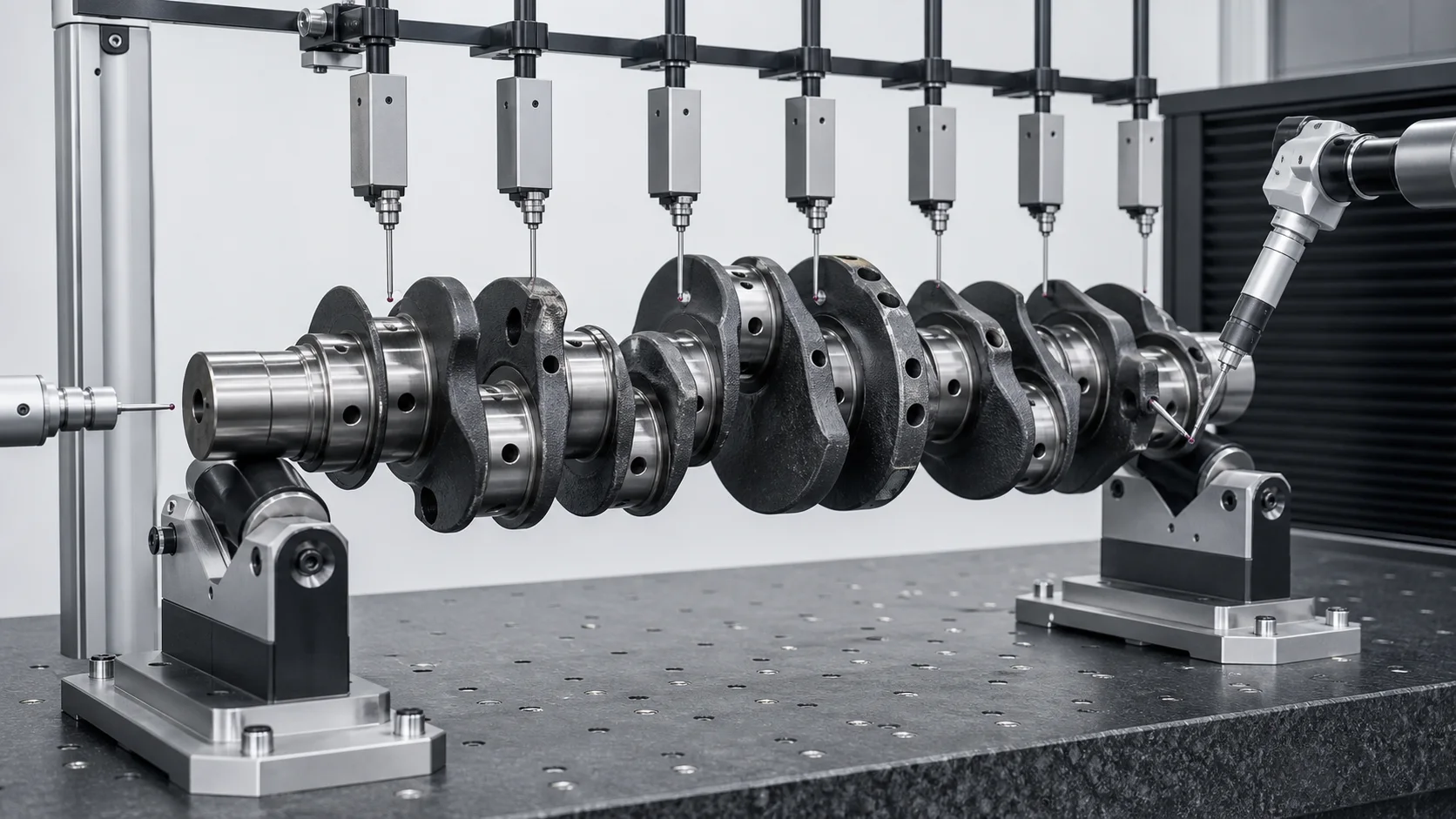
*Engineering koncept illustration: hovedjournalens bøjningskort og offset krumtap-geometri kræver separate målespor. De faktiske sondeplaceringer, rotationsmodel og funktionsmasker følger tegningen og måle-korrelationsplanen.*
| Målespor | Hvad det etablerer | Almindelig fejl, hvis misbrugt |
|---|---|---|
| Alle hovedtidsskrifter | Fællesakse løbe- og bøjningskort | Lokal lobing tolkes som global bøjning |
| Forreste og bageste hovedjournaler | Støtte/referenceakse | Slutskade skævvrider hele kortet |
| Knappinde | Diameter, kredsløb, slagtilfælde og faseforhold | Intentionel excentricitet tolkes som runout |
| Trykansigter | Aksial placering og ansigtsudløb | Grater eller lokalt slid dominerer læsningen |
| Fornæse og bageste flange | Forbundet komponent forhold | Funktionsfejl behandles som akselbøjning |
| Journal rundhed/cylindricitet | Lokal form | En lav TIR-værdi skjuler lokal formfejl |
| Filet- og oliehulsområder | Strukturel og overfladetilstand | En træthedskritisk defekt savnes |
| Balancekorrektionsplaner | Masseakse tilstand | Balance forveksles med geometrisk rethed |
Nidecs krumtapakselmålesystem klassificerer separat tap- og stiftdiametre. Marposs understøtter også endelige eller inter-operative dimensionelle, geometrisk og ikke-destruktiv måling. Den overførbare lektion er ikke en konkurrents nøjagtighedsværdi; det er behovet for en tegningsbaseret flerkarakteristisk inspektionsplan.
Vælg den korrekte supportreference
Krumtapakslens udløb kan måles:
- mellem kvalificerede centre;
- på ende hovedjournaler;
- på udvalgte V-ruller;
- i lejeækvivalente understøtninger;
- i en slibemaskine eller dedikeret måleopsætning.
Hegenscheidt lister udløbsmålinger med reference til centre eller V-blokke. Disse opsætninger giver ikke automatisk identiske resultater. Løsningen bør definere:
- fysisk støtte journaler og koordinater;
- centertilstand og kvalifikationsmetode;
- journalrundhedskompensation;
- aksial fastholdelse og tilladt bevægelse;
- krumtapvinkel og vinkelindeksering;
- gravitationssag til store krumtapaksler;
- sensorkraft og funktionsmasker;
- repeterbarhed i frigivet tilstand;
- korrelation til kværn og kundemåler.
Maskinen må ikke ændre henføringspunkter midtvejs i korrektionsløkken uden en etableret transformations- og korrelationsundersøgelse.
Tryk, Rulleretning og peening er forskellige processer
Kontrolleret trykudligning
En presse påfører en lokaliseret trepunkts- eller begrænset belastning ved en godkendt hovedjournal-region. Gleasons kraftige reparationsudstyr demonstrerer én markedsrute, hvor understøtter, overhead-hold-downs og en bevægelig ram lokaliserer arbejdet omkring en udvalgt journal. Det nøjagtige konkurrentlayout og kapacitet er ikke en StraighteningTech-specifikation.
Trykudretning kræver:
- en verificeret global bøjningsdiagnose;
- en godkendt belastningsvej gennem journaler/webs;
- kontaktværktøj med bred radius;
- kraft- og forskydningslofter;
- springback karakterisering;
- fuld aflæsning inden accept;
- efterkorrektion af revner og overfladetjek.
Rulleopretning
Hegenscheidt kombinerer vinkelafhængig dybvalsning, hovedleje TIR-måling og rulleudretning. Dette er en produktionsteknologi knyttet til filetbehandling og forslibningsgeometri. Det skal ikke beskrives som et generisk glattejern med flere rullestang.
Peening
Reparationsmarkedets SERP'er viser også peening-metoder. Peening ændrer lokal restbelastning og kræver en særskilt kvalificeret arbejdsinstruktion, operatørstyring, overfladeregler og inspektion. Det er ikke en automatisk erstatning for trykudligning, og denne artikel gør ikke krav på en universel peening-opskrift.
| Metode | Potentiel pasform | Primær kontrol | Antag ikke |
|---|---|---|---|
| Trykudligning | Godkendt bar krumtapaksel med sikker belastningsvej | Kraft, forskydning, støttespænd og frigivet TIR | Færdige fileter/journaler tåler kontakt |
| Rulleretning | Produktionsproces integreret med journal/filet operationer | Vinkelafhængig rullende og hovedjournalkort | Samme værktøj passer til enhver krankfamilie |
| Peening | Specialiseret reparationsmetode | Beliggenhed, intensitet, restspænding og overfladeinspektion | Hamring er i sagens natur sikkert eller gentageligt |
| Slibning | Lokal form/diameter og begrænset excentricitet på lager | Journalgeometri og lagerfjerning | Slibning kan fjerne enhver global bøjning |
| Udskiftning/afvisning | Sprække, brænde, utilstrækkeligt lager eller usikker lastvej | Teknisk disposition | Hver bøjet krumtapaksel kan repareres |
Byg et beskyttet kontaktkort
Standard No-Press og No-Support Zones
- vigtigste- og pin-journal filet radier;
- oliehuller og krydsboringer;
- offset crankpins, medmindre en dedikeret rute godkender dem;
- trykflader og færdige flangeflader;
- nøglebaner, splines, tråde og timing funktioner;
- balancehuller og lokale massekorrektionsfunktioner;
- skarpe baneovergange og tynde modvægtskanter;
- dybvalset, induktionshærdet, nitreret, svejset, belagte eller reparerede områder;
- revnet, brændt, ridsede eller varmepåvirkede overflader;
- færdige journaler uden beskyttet værktøjsgodkendelse.
Potentielt godkendte zoner
- ru eller halvfærdige hovedjournal lander med tilstrækkeligt lager;
- proceskraver eller offerforlængelser;
- designer-godkendte web/journal indlæsningsstier;
- dedikerede rullende kontaktsteder defineret af fremstillingsprocessen.
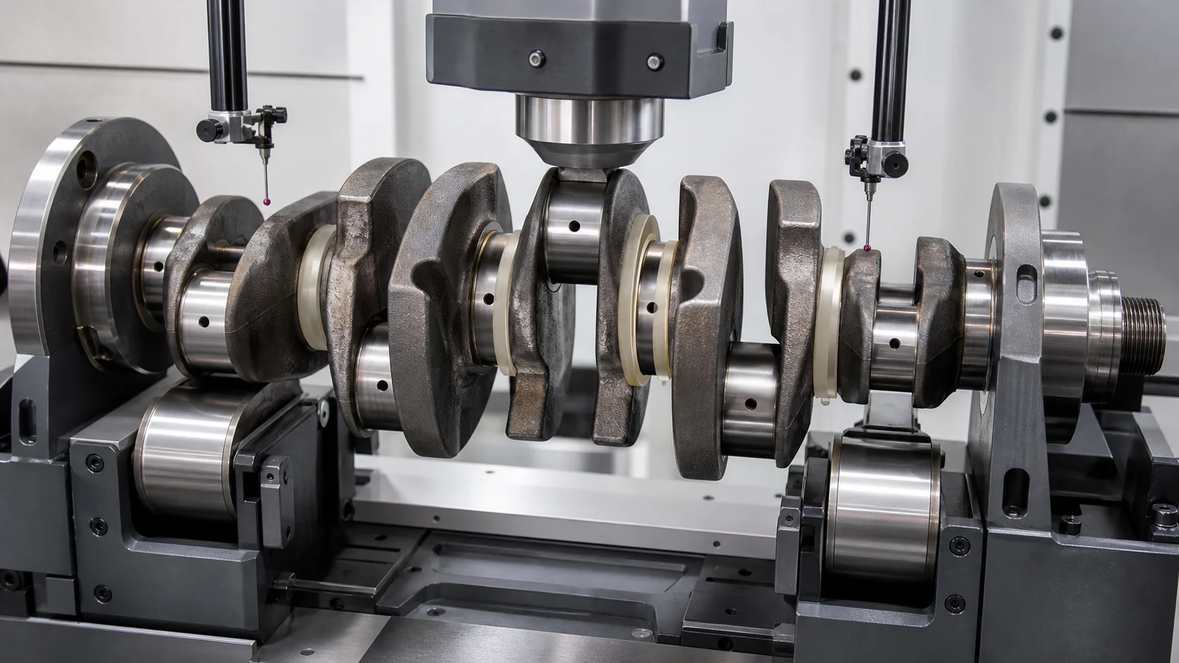
*Engineering koncept illustration: korrektion er begrænset til en godkendt hovedjournal-lastbane, mens fileter, oliehuller, krumtap og trykflader forbliver beskyttet. Billedet godkender ikke disse placeringer for en reel del.*
Det sikre kontaktkort skal opbevares med varenummer og tegningsrevision. En journal, der er sikker før slibning, kan blive en beskyttet endelig overflade senere.
Styr tilbagespring og krydskobling
En korrektion ved en hovedtap ændrer den elastiske form af tilstødende væv og journaler. Processen bør bruge et komplet hovedjournal-bøjningskort i stedet for at jagte én indikatortop.
For hvert korrektionstrin:
- rotere og måle alle kontrollerede hovedjournaler;
- adskille lokal form fra centerforskydning;
- identificer korrektionskoordinaten og krumtapvinklen;
- anvende en valideret trinvis belastning;
- rekord kraft og forskydning;
- aflæsse helt;
- roter og genmål hele kortet;
- tjek tilstødende krumtappinde, tryk/flange og beskyttede overflader;
- stoppe ved unormal stivhed, ikke-gentagelighed eller inspektionsindikation.
Belastet forskydning er ikke det færdige resultat. Kun det frigivne og gentagne kort kan afgøre, om tilbagespringet er blevet kompenseret sikkert.
Opretning vs slibning
Slibning kan generere journaldiameter, rundhed, cylindricitet og overfladefinish. Det kan også fjerne begrænset excentricitet, mens lageret er tilbage. Det kan ikke antages at genskabe en fælles hovedjournalakse, hvis den nødvendige lagerfjernelse ville overtræde størrelsen, filet- eller hårdhedsgrænser.
Beslutningen kræver et journal-for-journal lagerkort:
- indgående diameter og udløb;
- minimum færdig størrelse;
- resterende hårdt lag eller reparationsbelægning;
- tilladt undermåls-/reparationsklasse;
- filet- og trykfladegeometri;
- slibestøtte og datumopsætning;
- forventet lager efter frigivet opretning.
Marposs slibningsmålere i processen viser, at hoved- og stifttapdiametre har forskellige bevægelses- og målekrav. Opretning og slibning bør derfor planlægges som forbundne, men separate operationer.
Opretning vs balancering
Krumtapakselafbalancering korrigerer massefordelingen i forhold til definerede korrektionsplaner og, i motorapplikationer, kan være knyttet til bovvægt og roterende/frem- og tilbagegående masseantagelser. Det korrigerer ikke hovedjournalens koaksialitet, pin-journal form eller en bøjet global akse.
Hvis der rettes op, slibning, boring, fræsning, svejsning, plettering eller materialefjernelse sker efter afbalancering, den endelige balancetilstand skal verificeres igen. En krumtapaksel kan passere geometrisk udløb og stadig ikke balancekravet, eller pass balance, mens en hovedtapp er geometrisk forskudt.
Sprække, Overflade- og træthedsfølsom inspektion
At opfylde et løbemål er ikke tilstrækkeligt, hvis korrektion introducerer en skadelig indikation eller beskadiger en træthedskritisk overflade. Inspektionsplanen bør definere:
- forrengøring og visuel inspektion;
- magnetisk partikel, hvirvelstrøm eller anden godkendt NDT-vej efter materiale/proces;
- filet- og oliehulsdækning;
- journal bule, grænser for blå mærker og overfladefinish;
- slibe-forbrænding eller varme-skade inspektion;
- hårdheds-/dybdekontrol efter behov;
- acceptkriterier for forudgående svejsning, plettering eller reparation;
- inspektionstidspunkt før og efter korrektion/slibning;
- teknisk disposition for borderline indikationer.
Hegenscheidts procespåstand vedrørende udmattelsesstyrkebevarelse tilhører dets validerede rullesystem. Det kan ikke overføres til et trykudligningsforslag uden vores egne prøver, materialegodkendelse og træthedsfølsom validering.
Closed-loop krumtapaksel opretningsproces
1. Identificer delen
Indlæs den korrekte opskrift fra krumtapakselnummeret, motorfamilie, materiale, processtadiet, tegningsrevision og reparationshistorik.
2. Efterse og rengør
Rengør journaler og referenceflader. Efterse oliehuller, fileter, journal overflader, webs, næse og flange. Fuldfør påkrævet præ-proces NDT.
3. Kvalificere datoopsætningen
Bekræft centre eller supportjournaler, aksial placering, rotation og repeterbarhed af sæder.
4. Byg Multi-Journal-kortet
Mål hver hovedjournal gennem rotation. Optag pin-journal, fremstød, næse- og flangeegenskaber separat, hvor det kræves.
5. Klassificer afvigelsen
Adskil global bøjning fra journal-lobing, tilspidsning, slibelagerfejl, krumtapfase-/slagfejl, flangeskade, sprække, varmeforvrængning eller ubalance.
6. Vælg den godkendte metode og indlæsningssti
Vælg tryk, rullende, peening, slibning eller afvisning i henhold til den validerede delrute. Bekræft alle beskyttede zoner.
7. Anvend trinvis korrektion
Styrekraft, forskydning, krumtapvinkel og værktøjsposition. Stop ved unormalt svar.
8. Frigivelse og nymåling
Aflast helt og drej krumtapakslen igen. Opdater det komplette hovedtidsskriftskort i stedet for kun at kontrollere den rettede placering.
9. Inspicer og rute nedstrøms
Udfør efterkorrektion NDT/overfladekontrol og bekræft slibemateriale. Vej til slibning, endelig måling, afbalancering og montageeftersyn.
10. Optag resultatet
Butiksidentitet, opskrift revision, datum opsætning, før/efter kort, korrektionskoordinater, kraft-forskydningskurver, alarmer, eftersyn og disponering.
Foreslået krumtapakselretningscelle
Et projektspecifikt system kan omfatte:
- elektromekanisk eller hydraulisk korrektionsenhed dimensioneret ved prøvetestning;
- justerbare hovedjournalruller, centre eller V-støtter;
- servo rotation og krumtap-vinkel indeksering;
- flere udløbssensorer til hovedjournalkortet;
- separat krumtappind, fremstød, næse- og flangemålemoduler;
- brede udskiftelige pressesko og beskyttede understøtninger;
- automatisk hold-out logik for fileter, oliehuller og kontravægte;
- kraft/forskydningsovervågning og tilbagespringskompensation;
- belastning af tunge dele, løfte- og antirullesikkerhed;
- opskriftskontrol, sporbarhed og kvalitetsdataeksport;
- grænseflader til slibning, NDT og balanceposter.
Konfigurationen for en lille bilkrumtapaksel er ikke automatisk egnet til en stor marinekrumtapaksel eller værkstedsdel.
Prøveprøve og acceptplan
Repræsentative prøver bør dække:
- mindste og største krumtapaksellængde, svinge, masse og journaldiameter;
- forskellige hovedjournaloptællinger, krumtapslag og modvægtslayout;
- smedet, støbte og godkendte reparationsforhold;
- ru, forbearbejdet, varmebehandlet, dybvalsede og færdigslebne etaper;
- ekstreme materialer og hårdhed;
- forventede indkommende bøjningsformer og krumtapvinkler;
- journal form-fejl prøver, der ikke bør udløse korrektion;
- minimum slibelager;
- godkendte og forbudte kontaktzoner;
- kraft/forskydning og tilbagespringshylster;
- tilstødende journal krydskobling;
- Korrelation mellem hovedjournal og krumtapmåler;
- før/efter NDT og overfladeresultater;
- endelig slibning og balance verifikation;
- repeterbarhed og NOK routing.
Brug Udretningsprøvetest og acceptvejledning at adskille gennemførligheden, FEDT, SAT og produktionskapacitet.
Data påkrævet for et teknisk forslag
Angiv venligst:
- krumtapakseltegning og revision;
- motor/applikation og krumtapakselfamilie;
- et stykke smedet/støbt eller opbygget konstruktion;
- materiale, varmebehandling, hårdhed og filetbehandling;
- nuværende produktions- eller reparationsfase;
- hovedjournal, krumtap, fremstød, næse og flange dimensioner;
- slagtilfælde, stiftfase og modvægt layout;
- olie-hul og indre passage kort;
- indgående hovedjournaludløbskort efter vinkel;
- journal rundhed, cylindricitet og tilspidsning resultater;
- tegning af datums og kundemålingsopsætning;
- godkendte support/korrektionszoner og forbudte funktioner;
- formaling efter journal;
- sprække, brænde, overflade- og reparationsacceptkriterier;
- nedstrøms slibning, afbalancering og monteringsrækkefølge;
- krav til rapport og sporbarhed;
- repræsentative prøver til forsøg.
Ofte stillede spørgsmål
Kan en krumtapaksel rettes?
Nogle krumtapaksler kan rettes, men gennemførlighed afhænger af materiale, konstruktion, processtadiet, bøje form, slibemasse, filettilstand og en sikker læssevej. En revne, varmebeskadiget journal eller utilstrækkeligt lager kan i stedet kræve reparation eller afvisning.
Hvordan kan du se, om en krumtapaksel er bøjet?
Mål alle hovedjournaler i en kvalificeret støtteopsætning og adskil lokal rundhed fra centerforskydning. Crankpin orbital bevægelse, trykfladeudløb og flange/næsefunktioner kræver separate spor.
Kan du trykke på en krumtap eller filet?
Antag det ikke. Krumtap er offset-funktioner og fileter er træthedskritiske. Standardkontaktkortet beskytter krumtapper, fileter, oliehuller og færdige trykflader, medmindre en dedikeret proces er godkendt.
Er Peening Bedre End Press Straighting?
Det er forskellige reststress- og korrektionsprocesser. Den korrekte rute afhænger af krumtapakslens design, materiale, produktions-/reparationsstadie og validerede arbejdsinstruktioner. Ingen af dem bør vælges fra en generisk internetprocedure.
Kan slibning Fjern krumtapakselbøjning?
Slibning kan fjerne begrænset excentricitet inden for lagertillægget og generere endelig journalform. Det kan ikke sikkert løse enhver fællesaksefejl. Brug et journal-for-journal lagerkort.
Er krumtapakselbalancering stadig påkrævet?
Ja når specificeret. Opretning korrigerer geometrien; balancering korrigerer massefordelingen. Genbekræft balancen efter enhver operation, der ændrer geometri eller masse.
Skal en servicekrumtapaksel efterses for revner?
Ja, efter materialet, reparationsstandard og kundekrav. Opretning må ikke bruges til at skjule en revne, brænde, anfald eller tidligere reparationstilstand.
Byg løsningen omkring hovedtidsskriftets akse
Vi udvikler krumtapakselretningsløsninger omkring selve krumtapfamilien, hovedjournalens dato, offset krumtap geometri, processtadiet, beskyttede fileter, sikker lastvej, udgivet bøjningskort, slibemateriale og afsluttende inspektionssekvens. Maskinarkitekturen følger bevis fra tegninger og prøveforsøg – ikke en generisk akselopskrift eller en konkurrentspecifikation.
Next steps for a crankshaft project: bekræft maskinkonceptet med aksel, guide til valg af rør og profil glattejern, indram derefter business casen med omkostningsstruktur for en glattemaskine.
Send krumtapakseltegningen, processtadiet, materielle tilstand, indgående journalkort, slibetillæg, inspektionsstandard og repræsentative prøver. Vi kan derefter definere målestrategien, tryk eller rullevej, værktøjskort, korrektionskonvolut og sporbar acceptplan for din krumtapakselapplikation.
Relateret: Knastakseludretning følger samme datumlogik — se knastakseludretningsløsning.