
Vrtáky do betonu a vrtací korunky s rotačním kladivem kombinují dlouhé ocelové tělo se šroubovitými drážkami, karbidová řezná struktura a drážkovaná nebo profilovaná hnací stopka. Díky těmto vlastnostem se obrobek velmi liší od obyčejné kulaté tyče. Měřicí sonda může sledovat drážku namísto skutečné osy těla, zatímco nesprávně umístěná podpěra nebo lis může poškodit karbidový spoj, řezací hlava, okraj drážky nebo připojení SDS.
Řešení pro rovnání vrtáků do betonu proto musí být navrženo podle přesné řady vrtáků a výrobní fáze. Měl by měřit výkresem definovanou charakteristiku, opravte pouze schválené ocelové zóny a ověřte geometrii i stav po opravě.
Vrtáky do betonu nejsou jeden jednotný obrobek
Oficiální produktové řady vykazují podstatné konstrukční rozdíly. Bosch uvádí dvoubřité wolfram-karbidové desky, čtyřbřité celokarbidové hlavy, dva- a čtyřkřídlá těla, speciální svařované spoje hrotů a stopky SDS Plus. Hilti uvádí celokarbidové multi-břitové hlavy a čtyřnásobné šroubovice. DEWALT uvádí karbidové hroty, designy s otevřenou hlavou a prodloužená těla se čtyřmi břity.

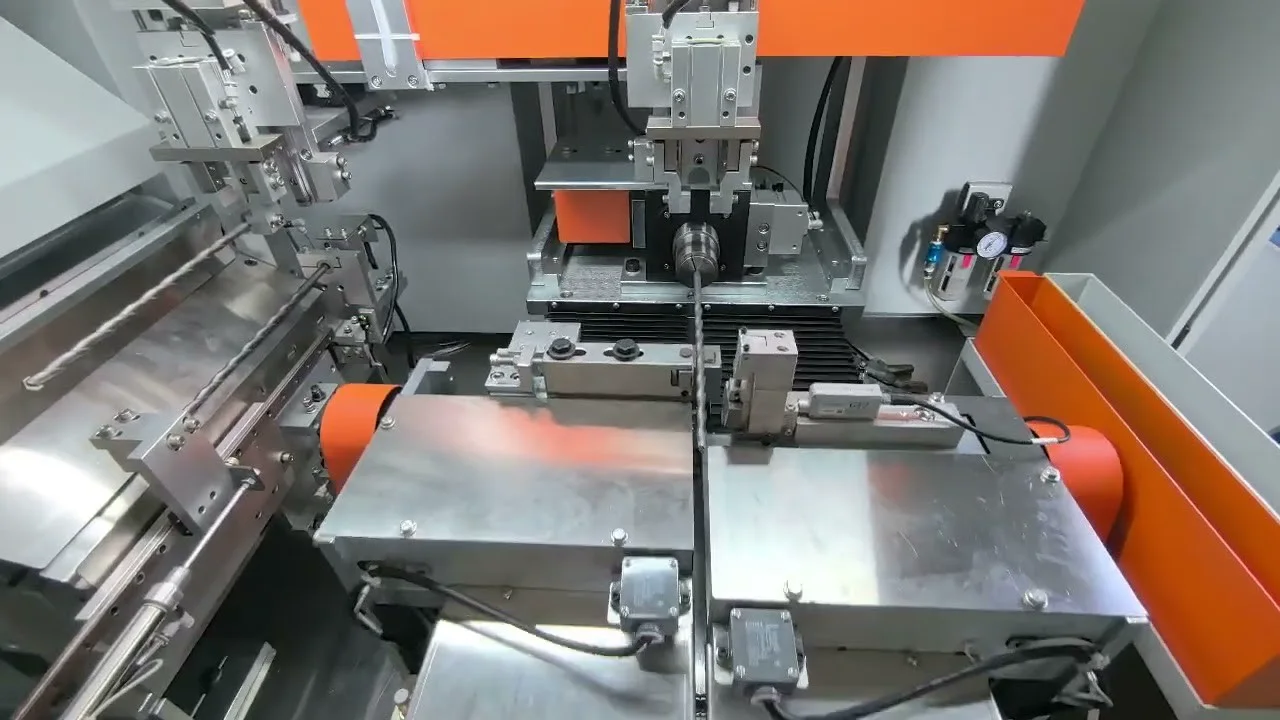
Obrázek je skutečným miniaturním rámečkem z videa projektu s elektrickým příklepem. Potvrzuje to drážkovaný vrták, přidržovací stanice a korekční mechanismus. Nezakládá bitový materiál, rozměry, přesnost nebo doba cyklu.
| Funkce obrobku | Důsledek narovnání |
|---|---|
| Pájená/svařovaná karbidová deska | Spoj a karbid musí normálně zůstat mimo oblast lisování/podpory |
| Celokarbidová multibřitová hlava | Křehká hlava vyšší hodnoty vyžaduje kontrolovanou manipulaci a ochranu proti nárazu |
| Dva- nebo čtyřbřitá šroubovice | Kontaktní měření se mění s axiální a úhlovou polohou |
| Snížené jádro nebo proměnná hloubka drážky | Tuhost v ohybu se mění podél pracovní délky |
| SDS Plus/Max nebo jiná stopka pohonu | Drážky a prvky pohonu nejsou jednoduchým válcovým podkladem |
| Kolo, plochý nebo patentovaný konec sklíčidla | Vyžaduje lokátor specifický pro variantu a definici házení |
| Tělo z kalené nebo povrchově upravené oceli | Odpružení změn, nebezpečí značení a prasklin |
Identifikujte fázi výroby
| Fáze | Potenciální účel | Hlavní omezení |
|---|---|---|
| Ocelový polotovar před drážkováním | Před obráběním/tvarováním stanovte přímou referenci | Finální vztah flétna/hlava ještě není k dispozici |
| Po formování flétny | Před nasazením tvrdokovu opravte deformaci tělesa | Změřte pomocí periodického spirálového profilu |
| Po tepelné úpravě | Opravte tepelné zkreslení | Tvrdost, limity odpružení a trhlin vyžadují ověření |
| Po uchycení tvrdokovu | Opravte deformaci montáže nebo spojování | Chraňte tvrdokov a pájený/svařovaný spoj |
| Po broušení/potahování | Seznamte se s finální geometrií | Velmi přísná povrchová a špičková ochrana |
Nejbezpečnější a nejschopnější fáze není automaticky poslední. Pokud proces opakovaně ohýbá bity po dřívější korekci, projekt by měl řešit tuto příčinu proti proudu nebo přesunout operaci rovnání do příslušné pozdější fáze.
Požadované vstupy projektu
| Vstup | Požadovaný detail |
|---|---|
| Výkres | Revize, ovládaná funkce, datum a tolerance |
| Bitová rodina | Průměr, celková/pracovní délka, počet fléten a profil jádra |
| Řezací hlava | Karbidová deska/plná hlava, počet fréz, společný typ a zakázané zóny |
| Shank | SDS Plus/Max, kolo, hex nebo vlastní geometrie připojení |
| Materiálová cesta | Třída oceli, kalení, připojení karbidu a sekvence povlakování |
| Příchozí ohyb | Velikost, rovinné a axiální rozložení z reprezentativních šarží |
| Závěrečná kontrola | Metoda přímosti/házení/profilu, rozchod, orientace a rozlišení |
| Rozsah výroby | Varianty, výstupní cíl, načítání, přechod a sledovatelnost |
Předchozí stránky neobsahovaly ověřenou velikost, tvrdost, přesnost nebo údaje o cyklu. Z videa by nemělo být nic vyvozováno.
Přímost, Házení a zarovnání špičky se liší
| Charakteristický | Co hodnotí | Potřebná definice |
|---|---|---|
| Rovnost těla | Tvar vybraného plošného prvku nebo odvozené osy tělesa | Metoda hodnocení řízené délky a flétny |
| Radiální házení | Variace povrchu při otáčení kolem nuly | Základní vlastnosti, poloha sondy/optické a úhlové vzorkování |
| Zarovnání mezi špičkou a stopkou | Vztah mezi řeznou hlavou a osou hřídele | Funkce hlavy, datum stopky a zóna přijetí |
| Profil flétny/vývod | Geometrie spirálového prvku | Axiální rozsah, úhlová referenční a profilová metoda |
| Funkční rotace | Chování ve schváleném sklíčidle nebo zkušebním vřetenu | Chucku, hloubka vložení, rychlost a měřená poloha |
ISO 1101 definuje jazyk pro geometrickou specifikaci, ale výkres zákazníka musí identifikovat skutečný toleranční prvek. Stroj nemůže „zajistit přímost nebo házivost“, dokud tato volba a datum nejsou explicitní.
Měření na flétnu je zásadní
Kontaktní sonda, která se dotýká rotující šroubovice, stoupá a klesá s flétnou. Tento periodický signál může být mnohem větší než vyhodnocovaný ohyb středové linie. Sloty a plošky SDS vytvářejí stejný problém na konci disku.
Koncepce měření by měla využívat jednu nebo více z následujících možností:
- definovaná hladká válcová plocha, pokud ji výkres poskytuje;
- řízené úhlové indexování pro měření stejného vztahu mezi drážkou a povrchem;
- více optických siluet a kalibrovaný model středové linie/profilu;
- bezkontaktní snímač ve schválených axiálních polohách;
- hlavní sklíčidlo nebo středy představující funkční základ;
- filtrování, které bylo ověřeno podle známých referenčních dílů, není vybrán pouze proto, aby graf vypadal hladce.
Síla sondy, poloha podpěry a upínací síla musí být také dostatečně nízké, aby se štíhlé tělo vrtáku neohnulo samotným měřením.
Doporučený proces rovnání s uzavřenou smyčkou
1. Identifikujte rodinu bitů
Operátor nebo automatizace ověří průměr bitu, délka, konstrukce drážky/hlavy a typ stopky. Recept vybere lokátor, podporuje, schválené měřicí polohy, korekční limity a zakázané zóny.
2. Nakládejte bez kontaktu s řeznými hranami
Zásobník, zásobníkové nebo podavačové nástroje představují jeden bit bez narážení karbidu na karbid. Hrany hlavy a drážky zůstávají bez tvrdých dorazů. Automatické podávání je nutné vyzkoušet se skutečnou délkou, povrch, olej a podmínky zapletení.
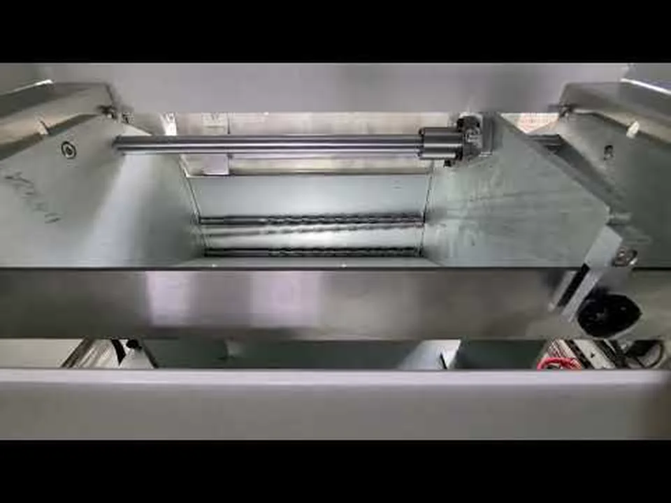
Tento snímek pochází ze správného veřejného videa konkrétního bitového stroje a zobrazuje oblast podávání. Nevykazuje výkon bezobslužného krmení, kapacitu nebo dobu přechodu.
3. Stanovte datum
Bit je držen schválenou hladkou zónou stopky, centra nebo funkční rozhraní. SDS sloty jsou indexovány, když ovlivňují lokátor. Upínač nesmí upnout bit do uměle rovného stavu.
4. Změřte vstupní geometrii
Kontaktní nebo bezkontaktní senzory shromažďují data pouze na ověřených pozicích a orientacích. Ovladač oddělí opakovatelnou stopu drážky/profilu od charakteristiky ohybu a uloží příchozí výsledek.
5. Vyberte podpěry a korekční bod
Podpěry a tiskový zákon o schválených ocelových zónách karoserie. Řezací hlava, karbidový spoj, okraj flétny, snížené jádro, přechod tepelného zpracování a funkce SDS jsou vyloučeny, pokud výkres a test vzorku výslovně neschválí kontakt.
6. Použijte omezenou bodovou korekci
Lis působí řízeným posuvem nebo silou. Vytvrzený, štíhlé a rýhované bity vyžadují stupňovitou korekci s maximální silou/zdvihem a limity iterace. Jedna závažná oprava není obecná strategie.
7. Znovu změřte pomocí stejného základu
Součást je přeměřena beze změny základní logiky. Další oprava je povolena pouze v rámci validovaného okna. Části s nadměrným vstupním ohybem, nestabilní hodnoty nebo neočekávané odpružení jsou odděleny pro kontrolu.
8. Ověřte stav a funkci
Konečné kontroly mohou zahrnovat geometrii, karbid/kontrola spoje, stav flétny a povlaku, kontrola trhlin a funkční rotace sklíčidla. Požadovaná sada se řídí výrobní fází a plánem kvality.
Video skutečného rovnání vrtáků do betonu
Následující video má název Automatic Straightening Machine for concrete bit na kanálu rovnacího stroje. Zobrazuje buňku vrtáku do betonu/rotačního kladiva s podáváním, přidržovací a korekční zařízení. Neprokazuje žádnou zvláštní přesnost, výstup, výnos nebo výsledek zákazníka.
Povrch, Karbid a ochrana spojů
| Riziko | Řízení |
|---|---|
| Tvrdokovový hrot odštípnutý manipulací | Oddělte díly a použijte nástroje pro vůli hlavy |
| Pájený/svařovaný spoj přetížený | Definujte vylučovací vzdálenost a maximální korekční moment |
| Okraj flétny promáčknutý | Používejte podpěry kompatibilní s profilem a schválené kontaktní zóny |
| Ztvrdlé tělo praská | Omezte příchozí ohyb a korekci; přidat požadovanou kontrolu trhlin |
| SDS slot použitý jako falešný základ | Vyhledejte na plochách schválených výkresem nebo na funkčním rozhraní sklíčidla |
| Sonda sleduje šroubovici | Použijte indexované/profilové nebo bezkontaktní měření |
| Označení nátěru nebo povrchové úpravy | Potvrďte kontaktní materiál, tlaková a kontrolní norma |
| Bit vyskočí z držáku | Kontrolujte upnutí a hlídejte korekční oblast |
Korekce bodu nebo rovnání válečků?
| Rozhodovací faktor | Bodová oprava může být preferována, když | Rovnání válců může být vyhodnoceno, když |
|---|---|---|
| Rozložení ohybu | Vysoké body lze měřit individuálně | Zakřivení je rozloženo podél dostatečně jednotného tělesa |
| Geometrie | Hlava, drážky a stopka vyžadují selektivní kontakt | K dispozici je souvislá dráha válečkového kontaktu |
| Měření | Je nutné přeměření v uzavřené smyčce | Před/po in-line měření lze ověřit výsledek |
| Povrch | Místní chráněný kontakt je přijatelný | Je povolen nepřetržitý válečkový kontakt |
| Produktový mix | Více variant vyžaduje specializované receptury/nástroje | Stabilní rodiny s vyšším objemem sdílejí ověřené nastavení role |
Tvrdokovová hlava automaticky nezakazuje veškeré rovnání, ale zužuje bezpečný kontakt a korekční okno. Proces je vybrán ze vzorků a výkresu, ne z univerzálního sloganu.
Vzorový plán testování a akceptace
Reprezentativní vzorky
- nejmenší tělo/jádro a nejdelší flexibilní varianta;
- počet každé flétny, provedení karbidové hlavy a rodina stopky;
- každý stav tepelného zpracování a povlaku;
- vzorky napříč skutečnou distribucí příchozích ohybů;
- více výrobních šarží, kde se deformace spoje nebo odpružení mohou lišit;
- hraniční části blízko zamýšleného korekčního limitu.
Požadované důkazy
| Záznam | Důkaz o přijetí |
|---|---|
| Částečná identita | Revize výkresu, varianta, cesta materiálu a šarže |
| Příchozí geometrie | Datum, orientace, polohy a naměřené hodnoty |
| Nástroje | Lokátor, podporuje, tiskové a zakázané kontaktní zóny |
| Historie oprav | Umístění, síla/posunutí a počet iterací |
| Finální geometrie | Stejné nastavení stroje plus korelace měřidla zákazníka |
| Stav hlavy/kloubů/flétny | Vizuál domluvený, zvětšený nebo NDT výsledek |
| Funkční výsledek | Otáčení sklíčidla nebo test po proudu, pokud je to nutné |
| Zkouška výroby | Měřený cyklus, stabilita krmení, změna a dostupnost |
Automatizace a změna
| Úroveň | Typický rozsah |
|---|---|
| Ruční načítání | Zatížení operátora; strojní opatření, opraví a ověří |
| Zásobník/zásobník | Řízená prezentace pro stabilní rodinu bitů |
| Automatická buňka | Krmení, identifikace, měření, oprava a třídění |
| Sledovatelná buňka | Část/šarže, recept, záznamy měření a korekce |
Změna průměru nebo délky může vyžadovat podpěry, sklíčidlo, poloha snímače a změny lisovacího nástroje. Přechod z dvoubřitého bitu SDS Plus na celokarbidový čtyřbřitý nebo jinou rodinu stopek není pouze změnou receptury PLC.
Co není univerzálním příslibem
Před kontrolou výkresu a ověřením vzorku, toto řešení neslibuje:
- jedna tolerance, doba cyklu nebo výnos pro každý vrták do betonu;
- že přímost a házivost jsou zaměnitelné;
- korekce každé příchozí velikosti ohybu;
- nulové poškození karbidu, spoj, flétna, povlakem nebo stopkou;
- automatické podávání pro každou délku a styl hlavy;
- že řízení PLC eliminuje software, nářadí nebo výměnné práce;
- fixní úspora práce nebo zlepšení výroby;
- bezpečná oprava použitých, vrtáky poškozené nárazem nebo prasklé.
Související aplikace
Recenze Řešení pro rovnání spojovacích prvků a nástrojů a Stroj na rovnání kulových čepů pro přilehlé nástroje a koncepty řízené korekce. Lékařské a chirurgické vrtačky zůstávají samostatnou rodinou obsahu, protože jsou součástí, povrch, regulační požadavky a požadavky na měření se liší.
Informace k zaslání návrhu
To turn this concrete drill bit guidance into a purchase decision, začít s návod k výběru rovnačky a tlakově otestujte čísla pomocí rozpočtový obrázek pro rovnací stroj.
Pošlete výkres a revizi, reprezentativní vzorky, rozsah průměr/délka/drážka/hlava/stopka, materiál a cesta kalení, způsob uchycení karbidu, výrobní fázi, distribuce příchozího ohybu, konečná charakteristika a datum, nastavení zákaznické kontroly, zakázané kontaktní zóny, pravidla kontroly hlavy/kloubů/flétny, výstupní cíl a preference načítání.
Kontaktujte StraighteningTech pro studii rovnání vrtáků do betonu na základě vzorku. Definujeme model měření, chráněné nářadí, korekční limity, rozsah automatizace a doklady o přijetí pro skutečnou rodinu bitů.
Často kladené otázky
Může sonda měřit přímo na spirálové žlábku?
Pouze metodou určenou pro daný profil. Rotující kontaktní sonda bude jinak sledovat šroubovici a může zaměnit periodickou změnu profilu za ohyb středové linie. Použijte řízené indexování, ověřený model profilu, hladký povrch nebo vhodné bezkontaktní měření.
Lze tvrdokovovou hlavu použít jako opěrný nebo lisovací bod?
Ve výchozím nastavení ne. Karbid a jeho pájený/svařovaný spoj jsou citlivé funkční zóny. Nástroje normálně působí na schválené oblasti ocelového těla s vylučovací vzdáleností od hlavy a kloubu.
Je stopka SDS spolehlivým rotačním datem?
Pouze pokud to výkres nebo funkční test tak definuje a lokátor reprodukuje schválené rozhraní sklíčidla. Jeho drážky a vlastnosti pohonu nejsou ekvivalentní úplnému válcovému povrchu.
Měl by být bit narovnán před nebo po upevnění tvrdokovu?
To závisí na tom, kde je zkreslení zavedeno a jaký konečný vztah je kontrolován. Dřívější narovnání nabízí bezpečnější kontakt; pozdější rovnání může opravit spojování nebo deformaci tepelného zpracování, ale vyžaduje přísnější ochranu a korekční limity.
Může jeden recept pokrýt dva- a čtyřbřité bity?
Ne automaticky. Světlost hlavy, podpis flétny, ztuhlost, datum, pozice podpěry a snímače se mohou lišit. Každá ověřená rodina potřebuje správnou kombinaci nástrojů a receptur.
Hranice technické reference
- Bosch SDS plus-1: https://www.bosch-professional.com/mz/en/sds-plus-1-hammer-drill-bits-2868938-ocs-ac/
- Bosch EXPERT SDS plus-7X: https://www.bosch-professional.com/gb/en/expert-sds-plus-7x-hammer-drill-bit-2867204-ocs-ac/
- Bosch SDS plus-3: https://www.bosch-professional.com/in/en/sds-plus-3-hammer-drill-bits-2867846-ocs-ac/
- Hilti TE-CX: https://www.hilti.com/c/CLS_POWER_TOOL_INSERT_7126/CLS_CONCRETE_MASONRY_DRILL_BITS_7126/r4429
- Vrták do zdiva DEWALT SDS Plus: https://www.dewalt.com/en-us/product/dw5443/916-x-10-x-12-rock-carbide-sds-plus-drill-bit
- MAE obrobky a aplikace: https://mae-group.com/en/workpieces-applications/
- ISO 1101:2017: https://www.iso.org/standard/66777.html
Tyto odkazy podporují rozmanitost konstrukce vrtáků a obecné principy geometrického/rovnání. Neprokazují, že výkon jiného dodavatele platí pro konfiguraci StraighteningTech.