
Brodogradnja sijalica ravna, koji se u nekim lancima nabavke naziva i HP profil ili Holland profil, je asimetrična ukrućenja koja se koristi sa pločastim strukturama. Njegova mreža i zaobljena sijalica ne ponašaju se kao pravokutna ravna šipka, simetrična greda ili željeznička šina pod mjerenjem i korekcijom.
Pouzdano rješenje za ravno ravnanje počinje s pet pitanja:
- Koji profil porodice, razred, dužina i uslovi isporuke su u obimu?
- Da li je traženi rezultat pravi profil proizvodnje, namjerno zakrivljeni okvir broda ili zavareni sklop?
- Kako su ivični nagibi, pramac van ravni, rotacija presjeka i lokalna promjena profila mjerena iz podataka definiranih crtežom?
- Koji web, sijalica, rub, obeležavanje, peskarene ili premazane površine mogu doći u kontakt sa mašinom?
- Kako će se potpuno pušten profil verificirati prije nizvodnog glodanja, zavarivanje ili montaža panela?
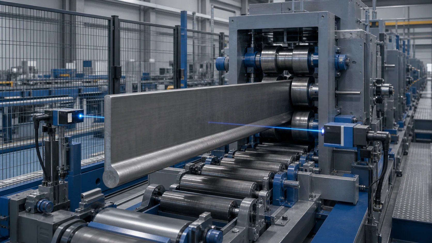
*Ilustracija inženjerskog koncepta uspravnog ravnog profila koji ulazi u liniju za ravnanje valjaka. To nije fotografija sa lokacije korisnika ili tvrdnja o performansama. Stvarni raspored rolni, sila, podrška, Rukovanje i granice prihvatanja zahtevaju specifikaciju kontrolisanog profila i ispitivanja uzoraka.*
Definirajte familiju proizvoda prije odabira stroja
| Porodica proizvoda ili procesa | Glavna razlika | Ruta na ovoj stranici |
|---|---|---|
| Bulb flat / HP profil | Ravna mreža sa zaobljenom sijalicom duž jedne ivice | Primarni opseg za ispravljanje |
| Holland profil | Imenovanje i dimenzionalne serije mogu se razlikovati prema dobavljaču ili klasi | Potvrdite crtež i presek prije dodjele recepta |
| Flat bar | Pravougaona i obično simetrična po širini | Odvojena familija alata i podataka |
| L ili T profil | Različita krutost presjeka, kontakt lands and twist odgovor | Recept za poseban profil |
| Zavareni sklop ukrućenja | Izobličenje zavarivanja djeluje kroz ploče i spojeve | Koristite rutu za zavarenu proizvodnju |
| Namjerno zakrivljeni okvir broda | Projektirana zakrivljenost je cilj, nije greška | Trasa formiranja/savijanja, ne direktna na nultu logiku |
| Railway rail | Profil glava-mreža-noga i zahtjevi za inspekciju željeznice | Koristite rješenje željeznica-željeznica |
ArcelorMittal opisuje bulb flats kao ploče za ukrućenje koje se koriste u brodogradnji. Fives javno opisuje ispravljač valjaka za cilindrične i ravne čelične profile u liniji za očuvanje brodogradnje, dok Stierli-Bieger nabraja ravne lukovice među profilima kojima rukuju sistemi za savijanje brodskih okvira. Zajedno ovi izvori uspostavljaju odvojene tokove rada ispravljanja i oblikovanja; oni ne čine jedan recept važećim za svaku sekciju ili fazu procesa.
Zamrznite fazu procesa
Nakon valjanja i hlađenja
Dolazna zakrivljenost može odražavati kotrljanje, asimetrično hlađenje, skladištenje ili transport. Kvalitet materijala, odjeljak, historija temperature i zaostalo naprezanje utječu na povratak. Prijedlog mora identificirati dolazno stanje umjesto pretpostavke da se svaki profil ponaša kao hladna ravna traka.
U liniji za očuvanje
Prije peskarenja može se integrirati ravna ravnanje, nanošenje premaza ili prajmera. Interfejs linije treba da zamrzne visinu transportera, orijentacija profila, stanje čišćenja, zahtjevi za označavanje i nizvodno takt. Za obloženi proizvod je potreban poseban pregled zaštite od kontakta.
Prije krajnjeg glodanja ili zavarivanja
Pravost i stabilan oslonac mogu uticati na pripremu kraja, montaža i automatizovano zavarivanje. Otpušteni profil treba verificirati prije nego što postane datum za drugi proces. Graebener's public profile-milling material confirms that bulb, T, kutni i ravni profili mogu ući u integrirane linije profila brodogradnje; to nije dokaz učinka ispravljanja.
Nakon zavarivanja
Nakon što je profil zavaren za ploču ili ugrađen u veći okvir, mijenja se put opterećenja i sistem podataka. Taj zadatak spada u rješenje zavarene proizvodnje i zahtijeva spoj, ulaze za inspekciju zona pod uticajem toplote i montaže.
Definirajte funkcionalne datume i orijentaciju
Najlakša površina valjka nije automatski referentna tačka za inspekciju. Plan mjerenja treba definisati:
- oznaka profila, crtanje preseka i orijentacija;
- uzdužno poreklo, krajnje stanje i isključene krajnje dužine;
- web lice ili središnja ravnina koja se koristi za pramca izvan ravni;
- ravna ili dizajnirana referenca ivice koja se koristi za nagib u ravni;
- krunica od sijalice, bulb root i web-to-bulb provjere prijelaza gdje je potrebno;
- rotacija sekcije ili uvijanje duž dužine;
- broj podrške, razmak, visina i odobrena kontaktna zemljišta;
- miniranje, skala, prajmer, označavanje i temperaturno stanje;
- ponovljivost nakon izdavanja, repozicioniranje i promjena orijentacije;
- correlation with the customer's final gauge or inspection system.
Čitaj ravnost osovine u odnosu na izbacivanje u odnosu na TIR za opštu razliku između stacionarnog geometrijskog profila i rotirajuće indikacije. Bulb pljosnati se obično pregleda kao potporni profil, ne kao rotirajuće vratilo.

*Inženjerski koncept ilustracija uzdužnog i presječnog mjerenja. To nije propisani raspored kolosijeka. Stvarni tragovi senzora, razmak nosača, referentne površine i prihvatljive trake zahtevaju kontrolisano crtanje profila i korelaciju merača korisnika.*
Odvojite modove greške prije ispravljanja
| Posmatrani signal | Mogući uzrok | Obavezna ruta |
|---|---|---|
| Glatko odstupanje u web ravni | Nagib ivica ili zamah | Kandidat za korekciju bočnog smjera |
| Glatko odstupanje normalno na web lice | Pramac izvan aviona | Kandidat za vertikalnu ili horizontalnu korekciju prema orijentaciji |
| Bulb i web reference se rotiraju duž dužine | Section twist | Mjerenje i korekcija specifično za torziju |
| Oštra lokalna promjena u blizini tačke udara | Pregib ili lokalno preopterećenje | Inspekcija i inženjerski pregled prije korekcije |
| Korijen lukovice ili oblik mreže mijenja se lokalno | Distorzija presjeka, defekt kotrljanja ili koncentrirani kontakt | Pregled profila; ne tretirajte samo kao središnji luk |
| Promjene signala s razmakom podrške | Sag, nestabilna potpora ili greška transportera | Zamrznite podešavanje i ponovite mjerenje |
| Geometrija odgovara predlošku okvira, ali ne odgovara pravoj liniji | Namjerna zakrivljenost okvira broda | Formiranje rute; ne ispravljajte na nulu |
| Greška se pojavljuje tek nakon zavarivanja | Skupljanje zavara ili ograničenje montaže | Trasa zavarene proizvodnje |
| Tijelo prolazi, ali kraj ne | Rezanje, krajnja greška vezana za hlađenje ili rukovanje | Konačna korekcija ili pregled obrade |
Zaštitite asimetrični presek
Zadane zaštićene ili pregledne zone
- zaobljena površina sijalice i prijelaz između sijalice i mreže bez kvalificiranog kontaktnog ispitivanja;
- tanke ili nepodržane web regije;
- rub namijenjen za kasnije zavarivanje ili precizno postavljanje;
- klasifikacija, oznake topline i sljedivosti;
- blasted, primed, premazane površine ili površine zaštićene od korozije;
- izrezi, zarezi, rupe, završne pripreme i obrađene zone;
- napukla, laminiran, jako skalirani, izdubljena ili oštećena područja.
Potencijalno odobrene kontaktne zone
- široke mreže ili lukovice odabrane analizom sekcija i reprezentativnim ogledima;
- izmjenjivi profilisani valjci, sedla ili šipke za presvlačenje prilagođene sekciji;
- nedovršene površine kada plan procesa eksplicitno dozvoljava kontakt;
- kasnije obrađene zone kada preostala zaliha i inspekcijski put to dozvoljavaju.
Svaka sila korekcije treba kompletan put reakcije. Zato što je sijalica odmaknuta od mreže, naizgled jednostavno opterećenje može dodati rotaciju sekcije ili lokalno označavanje ako se geometrija kontakta ne kontrolira.
Odaberite arhitekturu korekcije
Multi-Roll Ispravljanje
Valjna linija može odgovarati periodičnoj proizvodnji sa stabilnim presjekom, materijalno stanje i distribucija ulaznih grešaka. Naizmjenično kontrolirano savijanje može se pozabaviti kontinuiranom zakrivljenošću dok podržava integraciju linija. Inženjerski rad mora definirati orijentaciju rolne, aksijalno vođenje, kontaktni pritisak, stanje ulaska, ograničenja receptura i objavljena verifikacija za svaku kvalifikovanu porodicu.
Četvorsmjerna ili horizontalna korekcija pritiska
Presa sa pokretnim osloncima može odgovarati diskretnim krivinama, mješovite serije, krajnje zone ili profili koji zahtijevaju korekciju u više od jednog smjera. Prije promjene smjera opterećenja potrebni su alati i mjerenja specifični za profil.
Korekcija torzije
Twist zahtijeva mjerenje ugla duž presjeka, kontrolirani torzijski alat, obuzdavanje i ponovno mjerenje nakon potpunog otpuštanja. Uzastopno pritiskanje prividnog luka bez klasifikacije uvijanja može zamijeniti jedan način greške za drugi.
Savijanje okvira broda
Namjerno savijanje na šablonu brodskog okvira je proces oblikovanja. Stierli-Bieger javno opisuje savijanje ravnog okvira, uključujući promjene smjera savijanja i rukovanje dugim profilima. Ta arhitektura je relevantna kada je cilj kontrolirana zakrivljenost, ali se ne smije predstavljati kao ispravljanje na nultu liniju.
Čitaj ravnanje presa naspram ravnanja valjkom prije odabira porodice za korekciju.
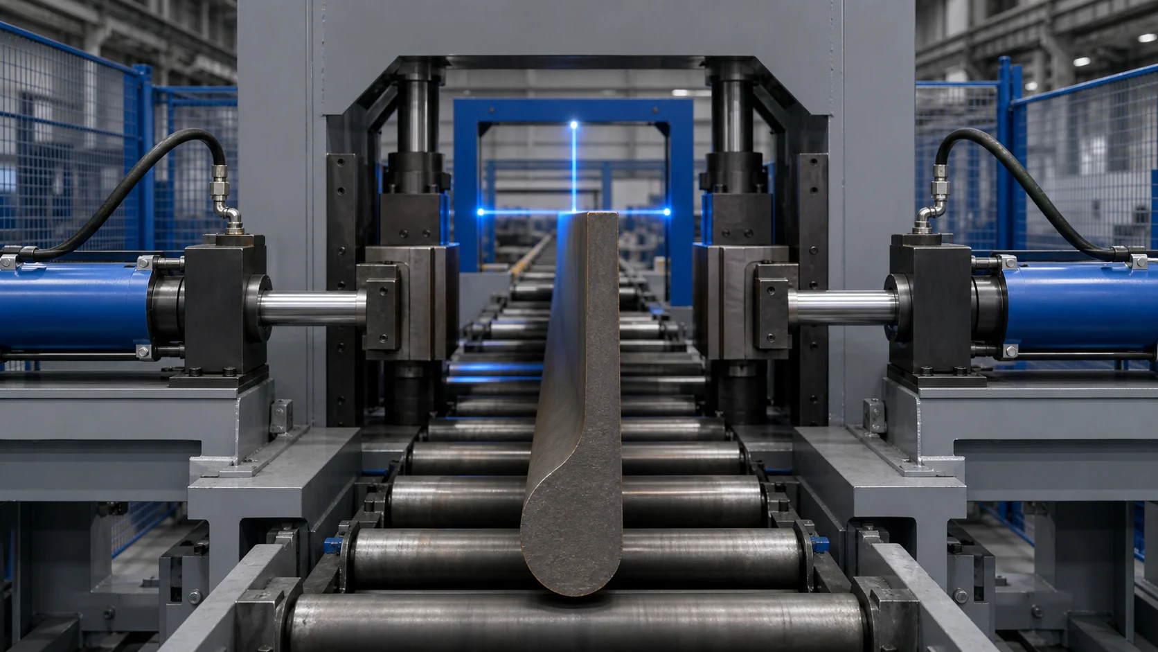
*Ilustracija inženjerskog koncepta podrške specifične za profil, bočna korekcija i nizvodno mjerenje. To nije univerzalni raspored mašine. Stvarna sila, raspon podrške, alat, ograničenja pomaka i ciklusa zahtijevaju inženjering projekta i probne uzorke.*
Integrirajte rukovanje dugim profilima
Sistem rukovanja je dio tačnosti ispravljanja. Koncept ćelije bi trebao uključivati:
- pogonski ulazni i izlazni transporteri na zamrznutoj referentnoj visini;
- vodilice koje čuvaju orijentaciju profila bez označavanja sijalice ili ruba;
- pozitivno aksijalno indeksiranje i kontrolirani položaji zaustavljanja;
- prilaz dizalicom za utovar, promjena podešavanja i oporavak;
- definirana metoda za promjenu smjera korekcije bez uvođenja novog savijanja;
- skala, Upravljanje medijima za pjeskarenje i krhotine premaza u blizini senzora i valjaka;
- čuvanje, blokade i siguran oporavak nakon prekinutog ciklusa;
- kontrola recepta koja sprečava da pogrešan odeljak koristi pohranjene postavke.
Potvrdite objavljeni profil
- Identifikujte profil, razred, dužina, faza procesa i sljedivost.
- Potvrdite da li je meta ravna ili namjerno zakrivljena.
- Pregledajte i očistite odobrene mjerne i kontaktne zone.
- Učitajte profil u zamrznutoj orijentaciji i stanju podrške.
- Izmjerite nagib, bow, twist i signali lokalne sekcije odvojeno.
- Klasifikujte grešku procesa, greška pri postavljanju, lokalna oštećenja i projektovana zakrivljenost.
- Odaberite rolnu, pritisnite, torzija, formiranje, ruta odbijanja ili inžinjerske revizije.
- Primijenite samo ograničenu korekciju koja je dodijeljena odobrenoj ravni i zoni.
- Potpuno otpustite i stabilizirajte profil.
- Ponovo izmjerite sa istim datumom, podrška i orijentacija.
- Ponovite samo unutar snage, pomak, overbend, iteracija i površinske granice.
- Popunite traženi profil, površine, označavanje i provjere nizvodnog procesa.
- Sačuvajte profil prije/poslije, recept, inspekcija i konačno rešenje.
Konfigurirajte ćeliju oko kvalifikovane porodice
| Funkcija ćelije | Zahtjev za ravnu sijalicu |
|---|---|
| Identifikacija | Serija profila, razred, dužina, faza procesa i sljedivost |
| Rukovanje | Dugi transporteri, kontrola orijentacije, indeksiranje i pristup dizalicom |
| Measurement | Edge camber, web bow, twist, krajeve i lokalne provjere sekcija |
| Klasifikacija | Kontinuirani naklon, sweep, twist, kink, lokalno izobličenje, greška pri postavljanju i projektovana zakrivljenost |
| Ispravka | Roll line, višesmjerna presa, torziona stanica ili formiranje trase |
| Zaštita | Lukovica/korijen, web, ivica za zavarivanje, oznake i površinska obrada |
| Verifikacija | Potpuno oslobođena geometrija plus provjere površine i nizvodnog procesa |
| Podaci | Profili prije/poslije, setup, sila/pomak, inspekcija i dispozicija |
Predlozi koji su nam potrebni
Prije odabira opreme pošaljite sljedeće:
- kontrolisane crteže profila i porodičnu listu;
- razred materijala, stanje isporuke i faza procesa;
- raspon dužine, šaržna mješavina i proizvodni takt;
- ravnu ili namjerno zakrivljenu nominalnu geometriju;
- camber, bow, twist, definicije prihvatanja kraja i lokalnog odeljka;
- dozvoljene i zaštićene kontaktne karte;
- distribucija dolaznih grešaka i poznati načini oštećenja;
- miniranje, premazivanje, obeležavanje, glodanje, sučelja za zavarivanje i montažu;
- visina transportera, smjer linije i raspoloživi pristup dizalicom;
- potreban konačni merač, interfejs izveštaja i sledljivosti;
- reprezentativno dobro, marginalni i odbačeni uzorci.
Uzorak-test prihvatanje prije puštanja u proizvodnju
Proba uzorka treba da pokrije stvarni profil porodice, stanje materijala i pravci korekcije. Trebalo bi provjeriti ponovljivost podrške, mjerna korelacija, označavanje kontakta, camber/bow/twist klasifikacija, springback, rukovanje, oslobođena geometrija i potrebne provjere nizvodno.
Koristite Ispitivanje uzorka za ispravljanje i vodič za prihvatanje da zamrzne testnu matricu i paket dokaza.
Inženjerska granica
Ispravljanje može ispraviti odobrenu geometrijsku grešku u odgovarajućim ravnim profilima. Ne popravlja pukotine ili laminacije, vratiti izgubljeni dio, kvalifikovati neprihvatljive zavarene spojeve, sama po sebi dokazuje usklađenost klasifikacije, ili zamijeniti kontrolirano oblikovanje kada je traženi proizvod namjerno zakrivljen.
Sila mašine, raspored rolne, raspon podrške, tačnost, vrijeme ciklusa, overbend i brojanje iteracija su rezultati prijedloga. Moraju biti iz porodice kontrolisanih profila, materijalno stanje, crteži, uzorci i mjerilo kupaca - ne iz tabele sa specifikacijama konkurenata.
Zatražite pregled ravnog ispravljanja sijalice za brodogradnju
Pošaljite tabelu profil-porodica, crteži, faza procesa, podaci i zahtjevi za kontakt, karte ulaznih grešaka i reprezentativni uzorci. Vratit ćemo predloženi datum i model podrške, mapa zaštićenog kontakta, koncept korekcije, plan rukovanja, uzorak-test matrice i konfiguraciju opreme za pregled.