
A sucker rod is not a short general-purpose steel bar and it is not a hollow drill pipe. It is a long, slender, cyclically loaded component in a rod-lift string. The plain rod body, forged or upset ends, wrench features, pin shoulders, threads and faces form one controlled workpiece. Material grade, κατεργασία με θερμοκρασία, επένδυση, corrosion exposure and service history can change the safe correction route.
A reliable sucker rod straightening solution must answer five questions before machine selection:
- Is the workpiece a new steel sucker rod, pony rod, used reclamation rod, polished rod, sinker bar or composite rod?
- How will full-length body bend be separated from self-weight sag, setup error, local wear and end-feature misalignment?
- Which plain body zones may contact rollers or supports, and which pin, ώμος, νήμα, face or coated zones are protected?
- Does the material and inspection condition permit correction, or should the rod be rejected before force is applied?
- How will the fully released rod be remeasured, inspected, graded and traced after correction?
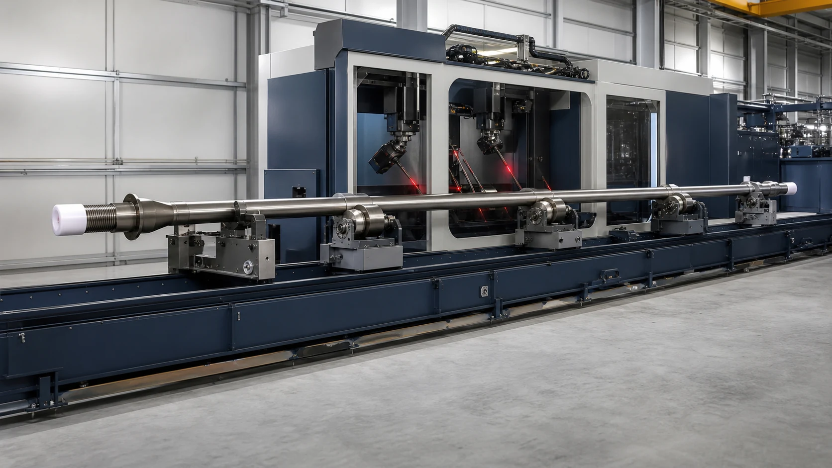
*Engineering concept illustration of a solid steel sucker rod in a long-bed measurement and straightening cell. It is not a customer-site photograph or performance claim. Actual supports, κυλίνδρους, sensors and acceptance limits require the controlled rod specification and representative sample tests.*
Define the Rod Family Before Selecting Equipment
SLB publicly distinguishes sucker rods, shorter pony rods and several coupling types. API identifies Spec 11B as covering sucker rods and rod-related products. Those product families should not be treated as interchangeable machine recipes.
| Rod or Component Family | Main Difference | This Page |
|---|---|---|
| Steel sucker rod | Long solid body with forged pin ends | Primary scope |
| Steel pony rod | Similar end geometry but shorter length | Same concept, separate support and recipe validation |
| Used sucker rod for reclamation | Unknown service, διάβρωση, wear and fatigue history | Inspection-first route only |
| Polished rod | Critical sealing surface and different service position | Separate surface-protection project |
| Fiberglass or composite sucker rod | Different stiffness, failure mode and connection design | Outside the steel-rod correction route |
| Sinker bar | Heavier section and different load role | Separate workpiece family |
| Coupling | Internally threaded connector, not a long rod | Inspect and handle separately |
| Drill pipe, casing or tubing | Hollow tubular with tool joints or connections | Use the oilfield tubular solution |
| Continuous rod or coiled rod | Different handling and installation system | Separate line concept |
This page focuses on solid steel sucker and pony rods. It does not claim that a pipe straightener, rebar machine or generic bar straightener automatically satisfies sucker-rod inspection and connection requirements.
Map the Complete Workpiece
The proposal should identify each controlled feature and its axial position:
- plain rod body;
- body diameter and any coating or wear-resistant treatment;
- upset or forged end section;
- body-to-upset transition;
- wrench square or wrench flats;
- pin shoulder;
- external pin thread;
- pin face;
- αναγνώριση, grade and traceability marks;
- installed rod guides or guide locations, if present;
- διάβρωση, wear, pitting or previous repair zones on used rods;
- coupling state: removed, loosely protected or outside the straightening scope.
NOV's public sucker-rod services sheet separates full-length visual inspection of the body, pin ends, thread and face. That is the correct mindset for straightening: a rod is not acceptable merely because a dial indicator on the middle body reads lower after processing.
Freeze the Manufacturing or Reclamation Stage
New Rod Before Heat Treatment
The material may be more responsive to correction, but later heat treatment can recreate distortion. Straightening here must support the next manufacturing operation and cannot replace final inspection.
Μετά από Θερμική Επεξεργασία
SLB states that its sucker rods are manufactured, heat-treated and tested. At this stage, βαθμός, σκληρότητα, residual stress and crack sensitivity become correction inputs. A recipe from untreated bar stock cannot be transferred without validation.
Before Final End or Surface Finishing
When process planning permits, remaining stock or later finishing may reduce marking risk and restore functional surfaces. The downstream operation must use a compatible datum and must not recreate bend.
Coated or Finished New Rod
SLB describes corrosion- and abrasion-resistant rod coatings for harsh conditions. A finished or coated rod needs an approved contact material, cleanliness standard and post-process surface inspection. The coating is not a sacrificial roller track.
Used Rod Reclamation
NOV publicly lists cleaning, magnetic particle inspection, electromagnetic inspection, full-length visual inspection, coupling removal, dimensional verification, demagnetization and grading for new and used sucker rods. Straightening belongs inside that inspection route; it cannot replace it.
Measure the Full Length Without Measuring Support Sag
Long slender rods deflect under their own weight. If support spacing, overhang or orientation changes, the measured profile changes even when the material has not. A full-length system therefore needs a frozen support model.
The measurement plan should define:
- axial origin and rod orientation;
- καταμέτρηση υποστήριξης, απόσταση, height and contact force;
- free-state or controlled-support straightness definition;
- full-length body profile at controlled axial stations;
- local body diameter, cross-sectional area or wear checks when required;
- pin-end, ώμος, thread and face inspection as separate features;
- allowable exclusion distance around upset transitions;
- coating or surface-condition influence on the sensor;
- temperature, cleaning and stabilization condition;
- repeatability after unloading, rotation and reclamping;
- correlation with the customer's inspection and grading system.
Read shaft straightness vs runout vs TIR before selecting a reported value. A stationary supported profile, a rotating runout trace and a free-state straightness result are not interchangeable.

*Engineering concept illustration of multi-station body measurement with protected pin ends. It is not a prescribed gauge layout. Actual support spacing, sag compensation, sensor tracks and end-feature checks require the rod specification and customer gauge correlation.*
Separate Bend From Damage and Setup Error
| Observed Signal | Possible Cause | Required Route |
|---|---|---|
| Smooth long-wave profile repeated after reclamping | Global body bow | Candidate for validated roller or press correction |
| Sharp local change at one position | Kink, impact, corrosion loss or local damage | Inspect and route to engineering or reject; do not average it into a global bend |
| Profile changes with support spacing | Self-weight sag or unstable support model | Freeze the support condition and repeat measurement |
| Trace changes after cleaning | Κλίμακα, έλαιο, coating deposit or debris | Clean and qualify the measurement surface |
| Body is stable but one pin end appears eccentric | Forged-end, shoulder or thread-axis problem | Inspect the end feature; body straightening may not correct it |
| High signal near the upset transition | Intended section change, local stiffness or forming error | Use a feature-specific exclusion and engineering review |
| Surface pit or crack indication coincides with bend | Corrosion or fatigue damage | Inspection/rejection route before correction |
| Rod is straight but rod-lift performance remains poor | Coupling, guide, tubing, ευθυγραμμία, loading or well-condition issue | Evaluate the complete rod string and artificial-lift system |
Straightening can change geometry. It cannot restore metal lost to corrosion, remove a fatigue crack or prove that a used rod is fit for another service cycle.
Build an Inspection Gate Before the Straightener
For new rods, the gate should confirm material grade, heat-treatment state, κατάσταση της επιφάνειας, traceability and the permitted correction stage.
For used rods, the gate is more restrictive. NOV publicly lists:
- cleaning and shot cleaning or blasting;
- full-length visual inspection of body, pin ends, thread and face;
- magnetic particle inspection;
- electromagnetic inspection;
- laser cross-sectional-area or outside-diameter verification;
- coupling removal and inspection;
- demagnetization;
- grading and color coding to API or customer requirements.
The exact inspection sequence and acceptance values belong to the customer's applicable standard and procedure. The machine should consume an inspection status, not assume that every bent rod entering the cell is safe to correct.
Protect the Pin Ends and Surface
Default No-Roller, No-Support or No-Press Zones
- external pin threads;
- pin face and shoulder;
- wrench flats or wrench square;
- upset or forged end;
- body-to-upset transition;
- identification and grade marks;
- rod guides or guide attachment zones;
- unapproved coating, plated or specially treated surfaces;
- corrosion pits, ρωγμές, gouges, wear flats or impact damage;
- coupling and thread protector unless the handling design explicitly supports it.
Potentially Approved Contact Zones
- cleaned plain rod-body lands with verified diameter and surface condition;
- unfinished body stock before final surface treatment, when the process plan allows it;
- broad polished rollers or replaceable inserts validated for contact pressure and marking;
- controlled support points selected away from transitions and known damage.
The safe map should be tied to the rod family, μήκος, βαθμός, επένδυση, end design and revision. A support that is acceptable for one pony rod may fall on a forged transition or guide location on another family.

*Engineering concept illustration of six smooth rollers acting on the plain rod body while the forged pin and thread remain outside the roller cassette. It is not a universal machine layout. Roller geometry, offset, contact stress and material response require sample validation.*
Choose the Correction Method From the Error Map
Multi-Roll Straightening
A cross-roll or staggered-roll system can be suitable for long-wave body curvature and continuous processing when the rod body provides a stable, approved roller track. Boyu Petro publicly markets roller straightening equipment for oilfield tubing, casing, drill pipe, steel pipe and sucker rods. That confirms an equipment category; it does not establish a universal sucker-rod recipe or inspection result.
The roller concept still requires:
- correct roll geometry for the solid rod body;
- controlled offsets and drive condition;
- protection of pin ends and forged transitions;
- surface-marking and coating trials;
- entry and exit support control;
- released full-length verification;
- an inspection route for new versus used rods.
Point Press Straightening
A measured press route may be considered for defined local body curvature when safe supports and a press point can be established. It needs force and displacement limits, a protected contact map, springback logic and fully released remeasurement. It is not appropriate for a sharp kink, crack indication or damaged end merely because the error is local.
Read press straightening vs roller straightening for the general method comparison, then apply the sucker-rod inspection and contact gates.
Reject, Replace or Regrade
Correction should stop when the rod has an unapproved crack indication, excessive corrosion or section loss, severe kink, damaged pin/thread/face, uncertain grade, unsuitable coating condition, unacceptable previous repair or another condition outside the approved reclamation procedure.
Design a Released-Part Closed Loop
The accepted value must be measured after the rod leaves the active roller or press load.
- Identify rod family, μήκος, βαθμός, end design and new/used status.
- Confirm the incoming inspection disposition and remove couplings when required.
- Clean the body and protect the pin threads and faces.
- Load the rod on the controlled full-length support system.
- Measure the body profile and separate end-feature or local-damage signals.
- Classify the error and select roller, τύπος, reject or engineering-review route.
- Apply only the bounded correction assigned to the approved body zone.
- Fully release and stabilize the rod.
- Remeasure the same profile under the same support condition.
- Repeat only within iteration, δύναμη, displacement and surface limits.
- Perform the required post-process visual, dimensional and NDT checks.
- Βαθμός, mark, trace and route the rod according to the approved quality procedure.
The controller should store both the geometry result and the quality disposition. A green straightness result must not override an NOK thread, surface or NDT result.
Configure the Production or Reclamation Cell
| Λειτουργία Κυττάρου | Sucker-Rod Requirement |
|---|---|
| Αναγνώριση | Rod family, βαθμός, μήκος, end design, coating and new/used status |
| Incoming inspection | Cleaning status, visual result, dimensional result, NDT status and disposition |
| Χειριζόμενος | Long-bed support without dragging, pin impact or thread damage |
| Μέτρηση | Full-length body profile with frozen support/sag model and end-feature separation |
| Διόρθωση | Protected multi-roll or measured press route with bounded settings |
| End protection | Thread caps or controlled handling outside the correction zone |
| Επαλήθευση | Fully released profile plus required body/end/surface checks |
| Quality routing | OK, remeasure, bounded rework, regrade, engineering review or reject |
| Ιχνηλασιμότητα | Rod ID, συνταγή, inspection status, initial/final profile, correction history and alarms |
Automation may include conveyors, walking beams, automatic end identification, καθάρισμα, laser measurement, roller adjustment, NDT integration and grading. The required configuration depends on rod-family mix and the customer's existing reclamation line; it should not be inferred from a generic bar-straightener specification.
Validate With Representative Rods
A sample program should include the actual variation expected in production:
- minimum and maximum rod or pony-rod length;
- all included body diameters and end geometries;
- material grades and heat-treatment states;
- coated and uncoated variants only when both are in scope;
- realistic long-wave bows and known local NOK conditions;
- new and used rods in separate validation groups;
- different corrosion, wear and cleaning conditions for used rods;
- repeated loading, rotation and reclamping trials;
- νήμα, face, ώμος, body-surface and NDT control samples;
- customer gauge and grading correlation.
The acceptance report should record sample count, rod identification, inspection status, support setup, measurement repeatability, initial and final profiles, roller or press settings, επαναλήψεις, surface findings, NDT results, grading outcome and excluded conditions.
Read straightening sample test and acceptance for the general FAT/SAT evidence structure. The sucker-rod project must add the applicable inspection and reclamation procedure.
What the Straightening Machine Does Not Prove
A lower body-bend reading does not by itself prove:
- compliance with API Spec 11B or a customer reclamation standard;
- restored fatigue life;
- removal of cracks, corrosion pits, wear or section loss;
- acceptable pin thread, shoulder or face condition;
- correct coupling make-up or connection integrity;
- compatibility with a particular well's load and corrosion environment;
- acceptable rod-guide, tubing or rod-string system condition;
- safe reuse of every used rod.
API officially identifies the 28th edition of Spec 11B as the current sucker-rods and rod-related-products specification. The purchaser and quality authority must provide the applicable edition, acceptance values and inspection procedure for the project. StraighteningTech should not invent or paraphrase inaccessible standard limits.
Information Needed for a Sucker Rod Proposal
Παρέχετε:
- rod and pony-rod drawings with revision;
- applicable standard and customer inspection/reclamation procedure;
- body diameter, length range, upset/end geometry and thread details;
- ποιότητα υλικού, κατάσταση σκληρότητας και θερμικής επεξεργασίας;
- επένδυση, guide and surface-protection requirements;
- new-manufacturing or used-reclamation stage;
- incoming cleaning, οπτικός, dimensional and NDT route;
- initial body-profile distribution and local NOK examples;
- straightness or runout definition, support condition and target;
- approved and prohibited contact zones;
- pin thread, face, shoulder and body acceptance requirements;
- όγκος παραγωγής, family mix and changeover frequency;
- φόρτωση, εκφόρτωση, coupling-removal and end-protection method;
- ιχνηλασιμότητα, grading and data-export requirements;
- representative OK and NOK samples.
StraighteningTech can then develop the measurement model, protected contact map, method selection, machine configuration, sample-test plan and acceptance evidence for the defined rod family. The result is a controlled sucker-rod process—not a generic promise to pass any bent oilfield rod through a bar or pipe straightener.