
Ένας χάλκινος ζυγός είναι ένας λειτουργικός ηλεκτρικός αγωγός, όχι απλώς μια μαλακή επίπεδη μπάρα. Η ευθύτητα επηρεάζει τη διατροφή, γροθιά, τομή, κάμψη, επένδυση, συναρμολόγηση και ευθυγράμμιση αρμών, ενώ βαθουλώματα, γρατσουνιές, οξείδιο, Η ζημιά στην επένδυση και οι παραμορφωμένες οπές μπορεί να επηρεάσουν την τελική ηλεκτρική διεπαφή.
Μια αξιόπιστη λύση ισιώματος χάλκινου ζυγού πρέπει να απαντά σε πέντε ερωτήσεις πριν από την επιλογή του μηχανήματος:
- Ποιο είδος χαλκού ή αλουμινίου, ιδιοσυγκρασία, πλάτος, πάχος, Το μήκος και η κατάσταση της ακμής είναι εντός πεδίου?
- Είναι το μέρος ακατέργαστο ίσιο απόθεμα, τρυπημένο κενό, επιμεταλλωμένος αγωγός, σκόπιμα λυγισμένη ράβδος ή σύστημα συναρμολογημένης ράβδου ζυγού?
- Πώς είναι flatwise τόξο, άκρο τόξο και συστροφή που μετρώνται από δεδομένα που καθορίζονται από το σχέδιο?
- Ποια πλατιά πρόσωπα, στενές άκρες, τρύπες, κουλοχέρηδες, επιμεταλλωμένα εδάφη και επιφάνειες αρμών μπορεί να έρθουν σε επαφή με εργαλεία?
- Πώς θα επαληθευτεί η πλήρως απελευθερωμένη ράβδος πριν από το επόμενο βήμα παραγωγής ηλεκτρικής ενέργειας?
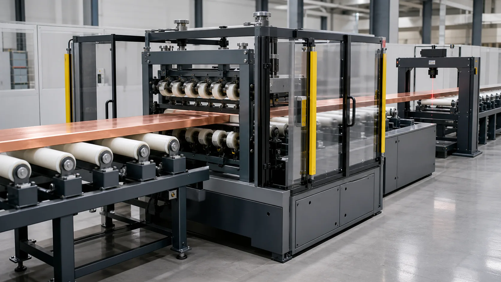
*Απεικόνιση έννοιας μηχανικής μιας συμπαγούς ορθογώνιας χάλκινης ράβδου που εισέρχεται σε μια προστατευμένη γραμμή ισιώματος και μέτρησης με ρολό. Δεν είναι φωτογραφία τοποθεσίας πελάτη ή αξίωση απόδοσης. Πραγματική γεωμετρία ρολού, πίεση επαφής, υποστήριξη, Τα όρια δύναμης και αποδοχής απαιτούν την προδιαγραφή ελεγχόμενου υλικού και εξαρτημάτων.*
Καθορίστε την οικογένεια διαύλου και τη διαδρομή διαδικασίας
| Οικογένεια ή Πολιτεία | Κύρια Διαφορά | Διαδρομή σε αυτήν τη σελίδα |
|---|---|---|
| Επίπεδη ράβδος ακατέργαστου χαλκού | Ίσιο κοντάκ πριν από τρύπες, υποδοχές και κάμψεις | Πρωτεύον πεδίο συνεχούς ευθυγράμμισης |
| Τρυπημένο ή κομμένο κενό | Τα χαρακτηριστικά μπορούν να αλλάξουν την ακαμψία και να περιορίσουν την επαφή | Μέτρηση με επίγνωση των δυνατοτήτων και διόρθωση σημείων |
| Κασσίτερος-, ασήμι- ή επινικελωμένο ζυγό | Τα εδάφη επικάλυψης και επαφής χρειάζονται ειδική προστασία | Εργαλεία χαμηλής σήμανσης και επιθεώρηση επιφάνειας |
| Δίαυλος αλουμινίου | Διαφορετικό υλικό, ελατήριο και συμπεριφορά επιφάνειας | Ξεχωριστή κατάλληλη οικογένεια συνταγών |
| Ελασματοποιημένη εύκαμπτη ράβδος | Πολυεπίπεδη κατασκευή και σχεδιασμένη ευελιξία | Εξωτερική λογική διόρθωσης συμπαγούς ράβδου |
| Σκόπιμα λυγισμένη ή στριμμένη ράβδος | Η γεωμετρία του σχεδίου περιέχει επίπεδη, άκρη, κάμψεις μετατόπισης ή στρέψης | Διαδρομή διαμόρφωσης και επαλήθευσης γωνίας |
| Συναρμολογημένη ράβδος λεωφορείων ή λεωφορείων | Υποστηρίζει, οι αρμοί και η μόνωση καθορίζουν τη γεωμετρία του συστήματος | Επιθεώρηση συναρμολόγησης; μην πιέζετε ως χαλαρό απόθεμα |
| Γενική επίπεδη ράβδος από χάλυβα | Διαφορετικές απαιτήσεις υλικού και λειτουργικής επιφάνειας | Ξεχωριστή λύση επίπεδης ράβδου |
Η KME παραθέτει δημόσια επίπεδες ράβδους χαλκού για εξοπλισμό διανομής, διανομής ισχύος, μετασχηματιστές και ηλεκτρικές μηχανές, με πολλαπλές γεωμετρίες και υλικές συνθήκες. ABB's busbar-system guidance treats flat copper busbars as current-carrying parts whose section, Τα στηρίγματα και η φόρτιση βραχυκυκλώματος ανήκουν στον ηλεκτρικό σχεδιασμό. Αυτά τα γεγονότα δημιουργούν υλική ταυτότητα, τελικές διεπαφές και κατάντη χρησιμοποιούν μέρος της εισόδου ευθυγράμμισης.
Παγώστε το στάδιο της διαδικασίας
Incoming Mill Bar
Το ίσιωμα του ακατέργαστου υλικού μπορεί να βελτιώσει τη σταθερή τροφοδοσία στο κόψιμο και το τρύπημα. Η εισερχόμενη δέσμη πρέπει να χωρίζεται με κράμα, ιδιοσυγκρασία, τμήμα και κατάσταση προμηθευτή. Μην δημιουργείτε μια συνταγή πίεσης για κάθε ράβδο χαλκού απλώς και μόνο επειδή η διατομή είναι ορθογώνια.
Πριν από το τρύπημα και το κόψιμο
Η διαμήκης ευθύτητα και η συστροφή επηρεάζουν την εμπλοκή του σφιγκτήρα, παρακολούθηση άκρων αναφοράς και θέση χαρακτηριστικών. Η Boschert δηλώνει ότι η διάτρηση με ράβδους χαλκού απαιτεί άκαμπτη επεξεργασία, ακριβής σύσφιξη και στήριξη και στις δύο πλευρές της περιοχής διάτρησης για να αποφευχθεί η συστροφή και η κάμψη. Χρησιμοποιήστε το ως απόδειξη για την ενοποίηση της διαδικασίας, όχι ως εγγύηση απόδοσης StraighteningTech.
Μετά από διάτρηση, Κοπή ή κατεργασία
Τρύπες, κουλοχέρηδες, Οι εγκοπές και η τοπική απώλεια διατομής μπορούν να αλλάξουν την ακαμψία και να δημιουργήσουν προστατευμένες ζώνες. Η μέτρηση δεν πρέπει να ερμηνεύει το ίδιο το χαρακτηριστικό ως σφάλμα επιφάνειας, και τα σημεία πίεσης δεν πρέπει να γεφυρώνουν ή να παραμορφώνουν ένα σχέδιο οπών.
Πριν ή Μετά την Επιμετάλλωση
Η διόρθωση πριν την επιμετάλλωση αποφεύγει την καταστροφή μιας τελικής επίστρωσης, αλλά πρέπει να διατηρεί το απόθεμα που επιτρέπεται για μεταγενέστερο φινίρισμα. Η διόρθωση μετά την επιμετάλλωση απαιτεί ειδική δοκιμή πίεσης επαφής και σήμανσης καθώς και επιθεώρηση των επιμεταλλωμένων περιοχών αρμών.
Σκόπιμη διαμόρφωση ζυγού
Επίπεδη κάμψη, κάμψη άκρων, Οι μετατοπίσεις και οι στροφές είναι ελεγχόμενες λειτουργίες διαμόρφωσης. Ο Stierli-Bieger περιγράφει δημοσίως τη μέτρηση γωνίας ζυγού, αποζημίωση ελατηρίου, Εργαλεία κάμψης και συστροφής άκρων. Αυτά τα στοιχεία υποστηρίζουν μια αποκλειστική διαδρομή διαμόρφωσης; ένας αγωγός που σχηματίζεται σκόπιμα δεν πρέπει να ισιώνεται ξανά στο μηδέν.
Μετρήστε χωριστά τρεις λειτουργίες γεωμετρίας
Flatwise Bow
Το πλατύ τόξο είναι φυσιολογική απόκλιση στο πλατύ πρόσωπο. Επειδή η ακαμψία κάμψης είναι χαμηλότερη προς αυτή την κατεύθυνση για πολλά ορθογώνια τμήματα, απόσταση υποστήριξης, Το αυτο-βάρος και η δύναμη ανιχνευτή μπορούν να αλλάξουν σημαντικά την ένδειξη.
Edgewise Bow
Το άκρο τόξο είναι απόκλιση κανονική προς τη στενή άκρη. Απαιτεί ένα σταθερό πλευρικό σημείο αναφοράς και επαρκή υποστήριξη έναντι του κυλίνδρου της ράβδου. Μια ράβδος μπορεί να περάσει έναν έλεγχο ευρείας όψης και να αποτύχει στην ευθυγράμμιση των άκρων σε ένα ντουλάπι ή ένα συγκρότημα.
Συστροφή
Το Twist είναι η αλλαγή της γωνίας τομής κατά μήκος της ράβδου. Το ύψος του πλατιού προσώπου σε έναν αισθητήρα δεν μπορεί να διακρίνει πλήρως το στρίψιμο από το τόξο, Σφάλμα στήριξης-ύψους ή τοπική διακύμανση πάχους. Χρησιμοποιήστε συζευγμένες αναφορές προσώπου/άκρων ή άλλη κατάλληλη γωνιακή μέθοδο.
Το σχέδιο μέτρησης πρέπει να ορίζει:
- κράμα, ιδιοσυγκρασία, τμήμα, μήκος και κατεύθυνση κόκκου/κύλισης όπου χρειάζεται;
- αξονική προέλευση, τελική κατάσταση και εξαιρούμενα μήκη άκρων;
- δεδομένα ευρείας όψης και ακμών;
- αριθμός υποστήριξης, απόσταση, κατάσταση και ύψος κυλίνδρου;
- διαθέτουν μάσκες για τρύπες, κουλοχέρηδες, εγκοπές και μετατοπίσεις;
- επιμεταλλωμένος ή τελειωμένος χάρτης επαφής-γης;
- θερμοκρασία, κατάσταση καθαρισμού και σταθεροποίησης;
- επαναληψιμότητα μετά την πλήρη απελευθέρωση και επανατοποθέτηση;
- συσχέτιση με το κατάντη εξάρτημα ή το μετρητή τελικής επιθεώρησης.
Ανάγνωση ευθύτητα άξονα vs runout vs TIR για τη γενική διάκριση μεταξύ σταθερής γεωμετρίας και ένδειξης περιστροφής. Μια γραμμή διαύλου είναι συνήθως ένα υποστηριζόμενο προφίλ, όχι ένα περιστρεφόμενο μέρος.
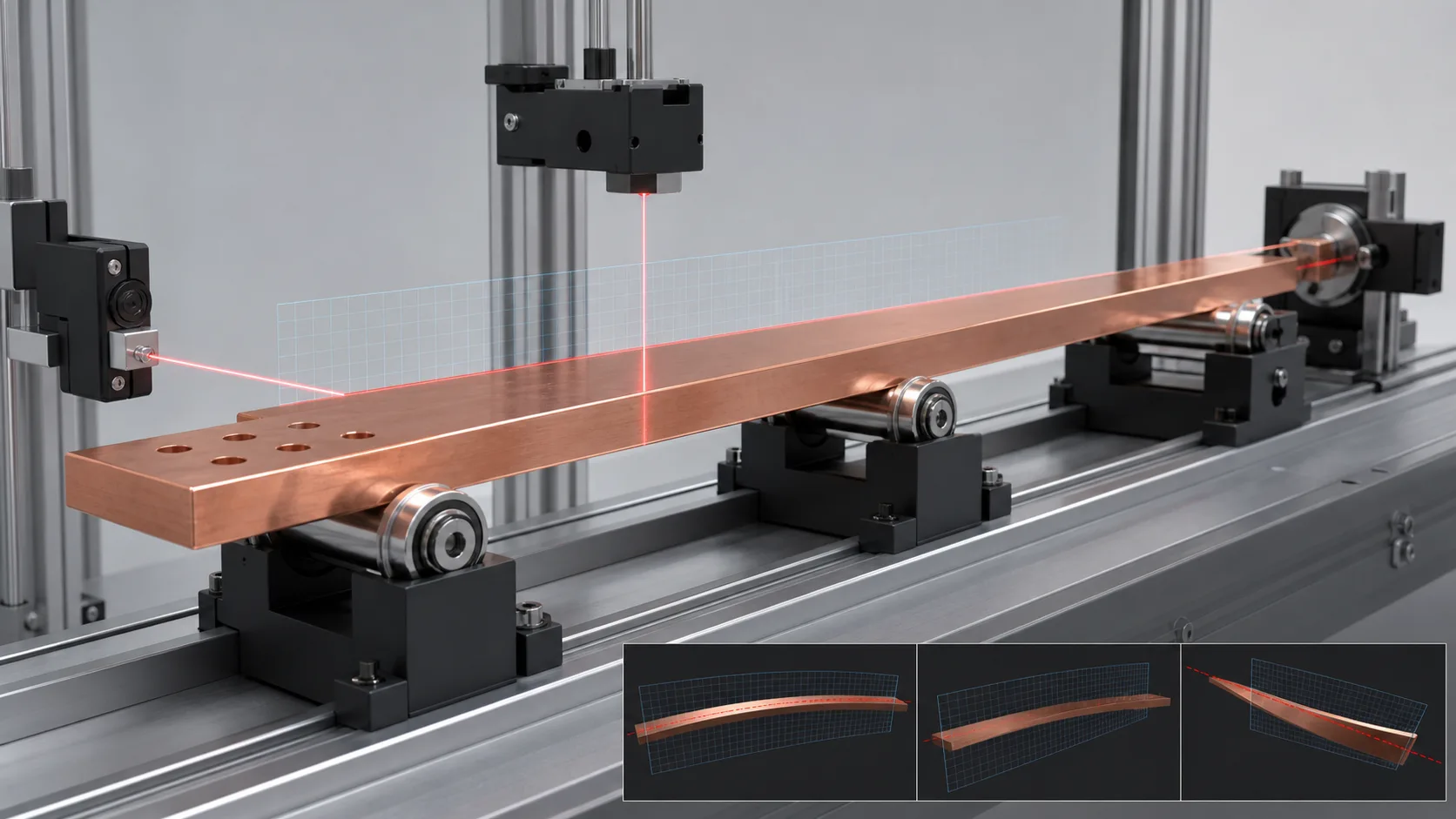
*Απεικόνιση έννοιας μηχανικής μέτρησης τριών τρόπων γύρω από μια απλή ορθογώνια τομή. Δεν είναι μια προδιαγεγραμμένη διάταξη μετρητή. Πραγματικές διαδρομές αισθητήρα, απόσταση υποστήριξης, Οι μάσκες χαρακτηριστικών και οι ζώνες αποδοχής απαιτούν την ελεγχόμενη σχεδίαση και τη συσχέτιση μετρητή πελάτη.*
Ταξινόμηση του σήματος πριν από την εφαρμογή δύναμης
| Παρατηρούμενο σήμα | Πιθανή αιτία | Απαιτούμενη διαδρομή |
|---|---|---|
| Ομαλή απόκλιση πλατιάς όψης επαναλαμβάνεται μετά την επαναφορά υποστήριξης | Επίπεδος φιόγκος | Υποψήφιος για διορθωτική ζαριά ή πόντος |
| Η απόκλιση ομαλής ακμής επαναλαμβάνεται μετά την επανατοποθέτηση | Πιο άκρο φιόγκο | Διόρθωση πλευρικής κατεύθυνσης με έλεγχο προσανατολισμού |
| Οι αναφορές προσώπου και άκρων περιστρέφονται κατά μήκος | Συστροφή | Μέτρηση και διόρθωση ειδικής στρέψης |
| Απότομη αλλαγή κοντά σε τρύπα ή εγκοπή | Τοπική παραμόρφωση διαδικασίας ή σφάλμα μάσκας χαρακτηριστικών | Επιθεώρηση χαρακτηριστικών πριν από τη διόρθωση |
| Το σήμα αλλάζει με απόσταση υποστήριξης | Γέρνω, σφάλμα ύψους κυλίνδρου ή ασταθές κύλινδρο ράβδου | Συνθήκη στήριξης κατάψυξης και επανάληψη της μέτρησης |
| Τοπικό υψηλό σημείο σε ένα τελειωμένο πρόσωπο | Αγριάδα, βαθούλωμα, συσσώρευση επιμετάλλωσης ή μόλυνση | Διαδρομή επιφάνειας/χαρακτηριστικού, όχι διόρθωση κεντρικής γραμμής |
| Η γεωμετρία ταιριάζει με το σχέδιο μετατόπισης ή συστροφής | Σκόπιμη διαμόρφωση | Διατηρήστε την ονομαστική γεωμετρία; μην ισιώσετε στο μηδέν |
| Τα εδάφη των αρμών δεν ευθυγραμμίζονται καλά μετά τη συναρμολόγηση | Γεωμετρία μέρους, αναπόσπαστο εξάρτημα, υποστήριξη ή σφάλμα στοίβας ανοχής | Διάγνωση συναρμολόγησης πριν από την τροποποίηση του αγωγού |
| Το σχέδιο οπών είναι παραμορφωμένο | Διάτρηση ή τοπική απόδοση | Επιθεώρηση χαρακτηριστικών; Το ίσιωμα δεν αποκαθιστά αυτόματα τη γεωμετρία της οπής |
Προστατέψτε τις αγώγιμες και τελειωμένες επιφάνειες
Προεπιλεγμένες προστατευμένες ζώνες ή ζώνες ελέγχου
- επιμεταλλωμένο, γυαλισμένα ή καθορισμένα εδάφη αρμών χαμηλής αντίστασης;
- τρύπες, κουλοχέρηδες, εγκοπές, καταβόθρες και χαρακτηριστικά με σπείρωμα;
- στενές άκρες όπου η συγκεντρωμένη επαφή μπορεί να κυλήσει ή να βαθουλώσει υλικό;
- έντυπος, σφραγισμένα ή σήματα ιχνηλασιμότητας;
- διεπαφές μόνωσης, μανίκια και επικαλυμμένες περιοχές;
- τοπικές στροφές, μετατοπίσεις και χαρακτηριστικά συστροφής που απαιτούνται από το σχέδιο;
- γρέζια, ρωγμές, αποκόλληση, σοβαρά βαθουλώματα ή υπερθερμασμένες περιοχές σε εκκρεμότητα απόρριψης.
Δυνητικά εγκεκριμένες ζώνες επαφής
- καθαρίστε ημιτελείς πλατιές όψεις που επιλέχθηκαν από μηχανική διαδικασίας;
- αντικαταστάσιμο πολυμερές, ίνα ή προφίλ με επιθέματα κατάλληλα για πίεση και σήμανση;
- περιοχές με άχρηστα άκρα ή μεταγενέστερες περικοπές, όταν το σχέδιο διαδικασίας επιτρέπει ρητά την επαφή;
- μη λειτουργικές επιφάνειες που αποδεικνύονται από αντιπροσωπευτικές δοκιμές επαφής.
Η «μη σήμανση» δεν είναι απόλυτος ισχυρισμός. Η δοκιμή επαφής θα πρέπει να ορίζει αποδεκτή εσοχή, γρατσουνιά, μεταφορά επίστρωσης, ρύπανσης και τα κριτήρια επιθεώρησης της ηλεκτρικής επιφάνειας.
Επιλέξτε την Αρχιτεκτονική Διόρθωσης
Ίσιωμα πολλαπλών ρολών
Μια γραμμή πολλαπλών κυλίνδρων μπορεί να ταιριάζει σε επαναλαμβανόμενες οικογένειες ακατέργαστων αποθεμάτων με ελεγχόμενη εισερχόμενη καμπυλότητα και σταθερό τμήμα. Η συνταγή πρέπει να ορίζει τη διείσδυση του ρολού, προσανατολισμός, υλικό επαφής, καθοδήγηση και στρατηγική πέρασμα από κράμα και ιδιοσυγκρασία. Η πλήρως απελευθερωμένη μέτρηση παραμένει το σήμα αποδοχής.
Point-Press Straightening
Μια οριζόντια ή κάθετη πρέσα μπορεί να ταιριάζει στις τοπικές στροφές, τελειωμένα κενά, μικτές παρτίδες ή τελικές ζώνες. Τα φαρδιά αντικαταστάσιμα στηρίγματα μπορούν να κατανείμουν την πίεση, αλλά η εγκεκριμένη διαδρομή φορτίου πρέπει να αποφεύγει τρύπες, κουλοχέρηδες, επιμεταλλωμένα εδάφη και μη υποστηριζόμενες άκρες.
Edgewise και Torsion Correction
Το τόξο και το στρίψιμο των άκρων χρειάζονται ειδική συγκράτηση και αίσθηση. Η περιστροφή μιας ράβδου μεταξύ επαναλαμβανόμενων επίπεδων πιέσεων χωρίς ταξινόμηση της λειτουργίας μπορεί να προκαλέσει ένα δεύτερο σφάλμα ή να καταστρέψει την επιφάνεια.
Κύτταρο σχηματισμού
Όταν ο στόχος περιέχει σχεδιασμένες στροφές, μετατοπίσεις ή περιστροφή, χρησιμοποιήστε μια συνταγή σχηματισμού με επαλήθευση γωνίας και ελατηρίου. Μην συνδυάζετε την αποδοχή ευθύτητας και την αποδοχή διαμορφωμένης γωνίας σε μία μέτρηση μηδενικής αναφοράς.
Ανάγνωση ίσιωμα πρέσας vs ίσιωμα με ρολό πριν επιλέξετε την οικογένεια διόρθωσης.
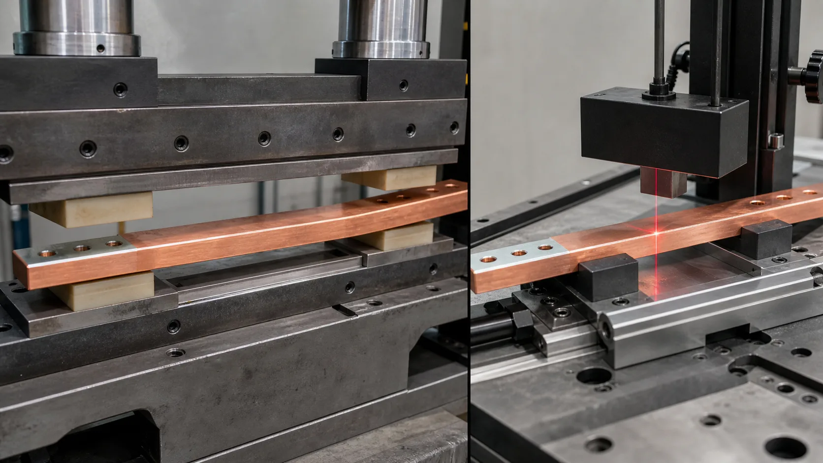
*Απεικόνιση έννοιας μηχανικής διόρθωσης σημείων με επίγνωση των χαρακτηριστικών με χρήση ευρειών αντικαταστάσιμων μαξιλαριών, ακολουθούμενη από απελευθερωμένη μέτρηση. Δεν είναι μια καθολική διάταξη μηχανήματος. Πραγματική δύναμη, σπιθαμή, υλικό εργαλείων, Τα όρια μετατόπισης και επιφάνειας απαιτούν μηχανική του έργου και δοκιμές δειγμάτων.*
Ενσωμάτωση τροφοδοσίας χωρίς προσθήκη νέου σφάλματος
Η έννοια του χειρισμού πρέπει να περιλαμβάνει:
- επίπεδοι μεταφορείς εισόδου και εξόδου με κυλίνδρους χαμηλής σήμανσης;
- οδηγοί που ελέγχουν τη θέση της ακμής χωρίς να σπάει χαλκό;
- σφιγκτήρες που δεν γλιστρούν, στρίψτε ή ανοίξτε τη ράβδο;
- ευρετηρίαση με επίγνωση των χαρακτηριστικών για τρύπες, υποδοχές και κομμένα άκρα;
- ελεγχόμενη εκφόρτωση ώστε τα μακρά εύκαμπτα τμήματα να μην κρεμούν ή συγκρούονται;
- καθαρισμός για να αποτρέψει τα ενσωματωμένα τσιπ και το οξείδιο από το να σημαδέψουν τις επιφάνειες;
- κλειδαριές συνταγής για κράμα, ιδιοσυγκρασία, τμήμα και στάδιο διαδικασίας;
- ασφαλής ανάκτηση μετά από εμπλοκή ή διακοπή του κύκλου διόρθωσης.
Επαληθεύστε την απελευθερωμένη μπάρα
- Προσδιορίστε το κράμα, ιδιοσυγκρασία, τμήμα, στάδιο και ιχνηλασιμότητα.
- Επιβεβαιώστε την ευθεία ονομαστική γεωμετρία σε σχέση με τις σχεδιασμένες στροφές ή μετατοπίσεις.
- Επιθεωρήστε και καθαρίστε τις ζώνες μέτρησης και τις εγκεκριμένες ζώνες επαφής.
- Τοποθετήστε τη γραμμή στη ρύθμιση παγωμένης υποστήριξης και προσανατολισμού.
- Μετρήστε το επίπεδο τόξο, φιόγκο με τις άκρες και στρίψτε χωριστά.
- Καλύψτε τις νόμιμες τρύπες, υποδοχές και διαμορφωμένα χαρακτηριστικά.
- Ταξινόμηση σφαλμάτων γεωμετρίας, ελάττωμα επιφάνειας/χαρακτηριστικού και σφάλμα ρύθμισης.
- Επιλέξτε ρολό, πιέστε το σημείο, συστροφή, σχηματίζοντας, απόρριψη ή διαδρομή αναθεώρησης μηχανικής.
- Εφαρμόστε μόνο την οριοθετημένη διόρθωση που έχει εκχωρηθεί στην εγκεκριμένη ζώνη και λειτουργία.
- Απελευθερώστε πλήρως και σταθεροποιήστε τη ράβδο.
- Επαναμετρήστε με το ίδιο σημείο αναφοράς και συνθήκη υποστήριξης.
- Ολοκληρωμένη επιφάνεια, επιμετάλλωση, έλεγχοι χαρακτηριστικών και κατάντη εξαρτημάτων.
- Αποθηκεύστε το προφίλ πριν/μετά, συνταγή, επιθεώρηση και διάθεση.
Διαμορφώστε το κελί γύρω από την κατάλληλη οικογένεια
| Λειτουργία Κυττάρου | Απαίτηση χαλκού-διαύλου |
|---|---|
| Αναγνώριση | Κράμα, ιδιοσυγκρασία, πλάτος, πάχος, μήκος, στάδιο και ιχνηλασιμότητα |
| Χειριζόμενος | Κύλινδροι χαμηλής σήμανσης, καθοδήγηση άκρων, ευρετηρίαση χαρακτηριστικών και ελεγχόμενη εκφόρτωση |
| Μέτρηση | Επίπεδος φιόγκος, άκρο τόξο, συστροφή, άκρα και καλυμμένες ζώνες χαρακτηριστικών |
| Ταξινόμηση | Συνεχής καμπυλότητα, τοπική συστροφή, συστροφή, Σφάλμα sag/setup και σχεδιασμένη γεωμετρία |
| Διόρθωση | Πολλαπλών ρολλών, πιέστε το σημείο, πλευρική διόρθωση, διαδρομή στρέψης ή διαμόρφωσης |
| Προστασία | Αγώγιμα πρόσωπα, επιμετάλλωση, τρύπες, κουλοχέρηδες, άκρες, σημάνσεις και ζώνες μόνωσης |
| Επαλήθευση | Απελευθερωμένη γεωμετρία συν επιφάνεια, έλεγχοι χαρακτηριστικών και κατάντη εξαρτημάτων |
| Δεδομένα | Προφίλ πριν/μετά, εγκατάσταση, δύναμη/μετατόπιση, επιθεώρηση και διάθεση |
Εισροές πρότασης που χρειαζόμαστε
Στείλτε τα παρακάτω πριν από την επιλογή εξοπλισμού:
- σχέδια ελεγχόμενων ανταλλακτικών και ακατέργαστων αποθεμάτων;
- κράμα χαλκού/αλουμινίου, απαιτήσεις πιστοποιητικού ιδιοσυγκρασίας και υλικού;
- πλάτος, πάχος, μήκος και οικογενειακό μείγμα;
- εισερχόμενα επίπεδα, κατανομή σφαλμάτων περιστροφής και περιστροφής;
- στάδιο της διαδικασίας: ακατέργαστος, τομή, γρονθοκοπημένος, κατεργασμένα, σχηματίστηκε, επιμεταλλωμένα ή συναρμολογημένα;
- τρύπα, σχισμή, εγκοπή, στροφή, χάρτες μετατόπισης και προστατευμένης επαφής;
- φινίρισμα επιφάνειας, επιμετάλλωση και αποδεκτά κριτήρια σήμανσης;
- ορισμοί τελικής ευθύτητας και διαμορφωμένης γεωμετρίας;
- χτύπημα γραμμής, κατεύθυνση τροφοδοσίας και διεπαφές ανάντη/κατάντη;
- μετρητή πελάτη, αναπόσπαστο εξάρτημα, απαιτήσεις αναφοράς και ιχνηλασιμότητας;
- αντιπροσωπευτικό καλό, οριακά και απορριπτικά δείγματα.
Αποδοχή δείγματος-δοκιμής πριν από την κυκλοφορία της παραγωγής
Η δοκιμή δείγματος θα πρέπει να καλύπτει το κράμα, ιδιοσυγκρασία, τμήμα, φάκελος σταδίου διαδικασίας και λειτουργίας σφάλματος. Θα πρέπει να επαληθεύει την επαναληψιμότητα της υποστήριξης, κατάταξη σε επίπεδο/άκρο/συστροφή, ελατήριο, αποφυγή χαρακτηριστικών, σήμανση επαφής, απελευθερωμένη γεωμετρία και επιθεώρηση κατάντη στερέωσης ή ηλεκτρικής επιφάνειας.
Χρησιμοποιήστε το δοκιμές δειγμάτων ευθυγράμμισης και οδηγός αποδοχής να παγώσει τη μήτρα δοκιμής και το πακέτο αποδεικτικών στοιχείων.
Μηχανικό Όριο
Το ίσιωμα μπορεί να διορθώσει εγκεκριμένο γεωμετρικό σφάλμα σε κατάλληλο συμπαγή ζυγό. Δεν αποκαθιστά παραμορφωμένες τρύπες, επισκευή ρωγμών, ανανέωση κατεστραμμένης επένδυσης, αφαιρέστε τη μόλυνση, αποδεικνύουν την αντίσταση της άρθρωσης, επανασχεδιάστε τα στηρίγματα βραχυκυκλώματος ή πιστοποιήστε το ολοκληρωμένο συγκρότημα διακοπτών.
Δύναμη μηχανής, διάταξη ρολού, εύρος στήριξης, ακρίβεια, χρόνος κύκλου, Η υπερβολική κάμψη και η μέτρηση επαναλήψεων είναι έξοδοι πρότασης. Πρέπει να προέρχονται από την ελεγχόμενη υλική οικογένεια, στάδιο της διαδικασίας, αναλήψεις, δείγματα και μετρητή πελάτη—όχι από πίνακα προδιαγραφών ανταγωνιστών.
Ζητήστε μια αναθεώρηση ισιώματος χάλκινου διαύλου
Στείλτε το υλικό και τον πίνακα ενοτήτων, αναλήψεις, διαδρομή διαδικασίας, προστατευμένος χάρτης επαφής, προφίλ εισερχόμενων σφαλμάτων και αντιπροσωπευτικά δείγματα. Θα επιστρέψουμε ένα προτεινόμενο μοντέλο δεδομένων και υποστήριξης, αρχιτεκτονική διόρθωσης, σχέδιο εργαλείων-προστασίας, μήτρα δείγματος-δοκιμής και διαμόρφωση εξοπλισμού για έλεγχο.