
Große nahtlose Stahlrohre können eine globale Biegung entwickeln, lokale Biegungen oder Handhabung von Verformungen nach dem Walzen, Wärmebehandlung, Transport und Lagerung. Wenn ein Rohr nicht gerade genug ist, Dies kann zu Problemen bei der Bearbeitung führen, Schweißen, Inspektion, Beschichtung, Montage oder Feldinstallation. Für lange und schwere Rohre, the correction process must also distinguish actual deformation from the deflection created by the pipe's own weight.
Dieser Lösungsvorschlag basiert auf einem Kundensortiment von OD 127 mm × 9.525 mm Wand zu AD 349.25 mm × 38.1 mm Wand, mit Längen von 1,828.8 Zu 12,192 mm. Es kombiniert kontrollierte Unterstützung, Messung in voller Länge, Richten und Nachmessen hydraulischer Spitzenpressen. Die aufgezeichnete Anforderung „1 in 1000 mm“ muss vor der Angebotserstellung geklärt werden; es wird vorläufig als möglich behandelt 1 mm Abweichung pro 1000 mm Messlänge, nicht als bestätigte Ein-Zoll-Toleranz.

Nahtlose Stahlrohre und Projektanforderungen
Das Projekt umfasst eine sehr breite Rohrhülle. Der Außendurchmesser ändert sich um fast das Dreifache, Die Wandstärke ändert sich um das Vierfache und die Gesamtlänge ändert sich um etwa das Vierfache 1.8 Zu 12.2 M. Diese Unterschiede wirken sich auf die Steifigkeit aus, Eigengewicht, Stützabstand, Messmethode, erforderliche Korrekturkraft und Materialhandhabung.
Benutzen 7,850 kg/m³ nur als vorläufige Schätzung der Stahldichte, Die kleinste angegebene Größe bei der kürzesten angegebenen Länge beträgt ungefähr 50 kg, während die größte angegebene Größe bei der längsten angegebenen Länge ungefähr wäre 3,564 kg, wenn diese Maximalmaße zusammen auftreten. Der tatsächliche Teileplan, Für die Dimensionierung des Lade- und Stützsystems sind Stahlgüte und zertifizierte Gewichte erforderlich.
| Projektelement | Kundeneingabe / Status |
|---|---|
| Werkstück | Nahtloses Stahlrohr |
| Außendurchmesser | 127–349,25 mm |
| Wandstärke | 9.525–38,1 mm |
| Länge | 1,828.8–12.192 mm |
| Materialqualität / Streckgrenze | Noch nicht bereitgestellt |
| Eingehende Verformung | Reichweite und Kurvenverteilung liegen noch nicht vor |
| Aufgezeichnete Geradheit | „1 Zoll 1000 mm“; Einheit, Messlänge und Akzeptanzmethode müssen bestätigt werden |
| Aktuelle Methode | Vom Kunden gemeldetes fachmännisches manuelles Richten |
| Hauptziel | Reduzieren Sie die Produktionszeit und die Abhängigkeit von erfahrener manueller Korrektur |
| Vorgeschlagene Methode | Schwerlasthydraulisches Punktpressenrichten mit gemessener Abstützung und Nachmessung |
| Maschinenmodell / Nennkraft | Durch technische Berechnung und repräsentative Stichprobenprüfung zu bestätigen |
Definieren Sie die lokale und allgemeine Geradheit, bevor Sie die Maschine auswählen
Eine Aussage wie „1 mm pro 1000 „mm“ beschreibt normalerweise eine lokale Geradheitsprüfung über eine definierte Messlänge. Es wird nicht automatisch die maximale Abweichung über den gesamten Wert definiert 12.2 m Rohr. Die Gesamtgeradheit kann relativ zu einer Sehne gemessen werden, Laserreferenz, spezifizierte Stützen oder eine andere Standardmethode. Diese beiden Kontrollen können zu unterschiedlichen Akzeptanzergebnissen führen und sollten nicht zu einer Zahl zusammengefasst werden.
Die Prüfbedingung muss auch die Rohrausrichtung und die Stützpositionen definieren. Ein langes Rohr biegt sich unter der Schwerkraft. If the machine supports it at different points from the customer's inspection station, Die beiden Systeme können unterschiedliche Werte melden, selbst wenn keine Messung fehlerhaft ist. Die Messgerätekorrelation erfordert daher dieselbe Datumslogik, vereinbarte Stützanordnung und eine wiederholbare Methode zur Trennung der Eigengewichtsverformung von der permanenten Biegung.
| Kontrollelement | Erforderliche Definition |
|---|---|
| Lokale Geradheit | Zulässige Abweichung und genaue Messlänge, potenziell 1000 mm |
| Gesamtgeradheit | Anforderung und Messmethode für die gesamte Sehne/Achse |
| Bezugspunkt messen | Rohr-Außendurchmesser, Mittellinie, Referenzgeneratoren oder spezifizierte Endmerkmale |
| Support-Bedingung | Nummer, Position, Höhe und Kontaktart der Stützen |
| Orientierung | Feste Taktposition oder Drehung um definierte Winkel |
| Ovalität / Durchmesser | Nur erforderlich, wenn die Zeichnung oder Norm dies steuert |
| Oberflächenakzeptanz | Keine unzumutbaren Dellen, lokale Abflachungen oder Stütz-/Pressstellen |
Warum große nahtlose Rohre schwer zu richten sind
Das Werkstück ist hohl, Daher wirkt die Presse nicht auf einen festen Abschnitt. Ein schmaler Stempel oder eine falsch positionierte Stütze können zu lokalen Eindrücken führen, Abflachung oder Ovalität, auch wenn sich der Längsbogen verbessert. Konturierte Sättel müssen den Kontakt über eine geeignete Fläche verteilen, und die zulässige Kontaktspannung muss für den tatsächlichen Außendurchmesser validiert werden, Wandstärke, Grad und Temperatur. Die Abschnittserhaltungsregeln für kleinere Hohlteile werden in behandelt Richten dünnwandiger Rohre.
Der Längen- und Gewichtsbereich stellt eine zweite Herausforderung dar. A 12 m Rohr kann nicht als kurzes Teil behandelt werden, das zwischen zwei festen Stützen platziert wird. Zur Kontrolle des Durchhangs sind möglicherweise mehrere angetriebene oder verstellbare Stützen erforderlich, Bewegen Sie das Rohr durch die Mess- und Presspositionen und verhindern Sie ein unkontrolliertes Wegrollen. Das Supportsystem ist Teil des Mess- und Richtprozesses, nicht nur Materialtransport.
| Werkstückspezifische Herausforderung | Risiko | Erforderliche Kontrolle |
|---|---|---|
| Hohler kreisförmiger Abschnitt | Beulen, Abflachung oder Ovalität beim Punktpressen | Breit konturierter Pressschuh und Sättel; Kraft-/Weggrenzen |
| 1.8–12,2 m Längenbereich | Das Eigengewicht führt zu falschen Messwerten für die Geradheit | Definiertes Stützmodell und wiederholbare Messung über die gesamte Länge |
| Bis OD 349.25 × 38.1 mm | Hohe und variable Korrekturkraft | Sorten-/Ertragsdaten, Biegeprofil, Berechnung und Probenvalidierung |
| Potenziell tonnenschweres Teil | Unsichere oder langsame manuelle Positionierung | Angetriebene Rollen, Anti-Roll-Vorrichtungen, Kran-/Portalschnittstelle und geschützte Bewegung |
| Mehrere lokale Kurven | Eine Korrektur verändert benachbarte Abschnitte | Biegekarte in voller Länge und kontrollierte Korrektursequenz |
| Große Familie | Übermäßiges Umrüsten oder falsches Werkzeug | Größenspezifische Rezepturen, verstellbare Stützen und geprüfter Werkzeugsatz |
| Kompetenter manueller Prozess | Bedienerabhängiger Druckpunkt und Hub | Gemessene Biegestelle, kontrollierte Korrektur und erneute Überprüfung |
Empfohlene Richtmethode
Für große Rohre mit lokaler oder mehrpunktiger Biegung, Ein hydraulisches Dreipunkt-Press-Richtkonzept ist der bevorzugte Ausgangspunkt. Das Rohr wird auf zwei oder mehr kontrollierten Sätteln getragen, Das Biegeprofil wird gemessen, und ein hydraulischer Stößel führt an einer zugelassenen Stelle einen Überbiegehub aus. Abhängig vom endgültigen Layout, Das Rohr kann durch einen stationären Pressenrahmen geführt werden oder ein Pressen-/Messrahmen kann sich entlang des Rohrs bewegen.
Für die kontinuierliche Produktion gleichmäßiger Rohrgrößen und verteilter Krümmungen eignet sich möglicherweise eine Mehrwalzen-Richtmaschine besser. Für einen breiten Mix an großen Durchmessern ist es nicht automatisch die beste Wahl, dicke Wände und örtliche Biegungen. Bei der endgültigen Methodenauswahl muss der Durchsatz berücksichtigt werden, Größenmix, Materialqualität, eingehende Verformung, Ovalitätsrisiko und ob das Rohr sicher gedreht werden kann. Ölleitungen und Gehäuse Folgen Sie einer entsprechenden OCTG-spezifischen Route.
Vorgeschlagener automatischer Richtprozess
Das zugehörige 243-Sekunden-Video zeigt ein großes Rohr in einer schweren vertikalen hydraulischen Pressstation mit einer erhöhten Serviceplattform und mehreren Stützelementen. Es ist ein nützlicher Beweis für das Ausmaß, Herausforderung der Pressenarchitektur und der Rohrhandhabung. Es ist kein sichtbarer Beweis für die Messtechnik, Nennkraft, endgültige Toleranz, automatischer Korrekturalgorithmus oder Produktionszyklus, Daher unterliegen diese Details weiterhin der Projektbestätigung.
| Schritt | Verfahren | Technischer Zweck |
|---|---|---|
| 1 | Rohridentifikation und Rezeptauswahl | Passen Sie den Außendurchmesser an, Wand, Länge, Grad, Toleranz und Werkzeugausstattung |
| 2 | Beladung und Anti-Roll-Positionierung | Übertragen Sie ein schweres Rohr sicher auf kontrollierte Stützen |
| 3 | Einrichtung der Stützhöhe und Festlegung des Bezugspunkts | Erstellen Sie eine wiederholbare Bedingung für die Messung langer Rohre |
| 4 | Erste Messung in voller Länge | Lokale und allgemeine Biegung vor der Korrektur kartieren |
| 5 | Biegeberechnung und Korrektursequenz | Druckpunkt auswählen, Stützspanne, Orientierung und Erstschlag |
| 6 | Rohr- oder Rahmenindizierung | Richten Sie den ausgewählten Bogen an der hydraulischen Korrekturstation aus |
| 7 | Kontrolliertes hydraulisches Überbiegen | Korrigieren Sie das Rohr mit Kraft, Hub- und Ovalitätsgrenzen |
| 8 | Neumessung und adaptive Korrektur | Schließen Sie den Kreislauf oder stoppen Sie an der validierten Prozessgrenze |
| 9 | Abschließende Geradheits-/Ovalitätsprüfung | Überprüfen Sie jedes erforderliche Merkmal mit der vereinbarten Methode |
| 10 | Datenaufzeichnung und -entladung | Speichern Sie Ergebnisse und bewegen Sie OK/NOK-Rohre sicher aus der Zelle |
Laden, Unterstützung und Positionierung
Der Rohrtransport erfolgt per Kran, Portal, Hubbalken oder angetriebenes Rollensystem je nach tatsächlichem Gewicht und Pflanzenfluss. Anti-Roll-Vorrichtungen und positive Anschläge sind unerlässlich, da sich ein großes rundes Werkstück unerwartet bewegen kann. Stützen sollten in Position und Höhe verstellbar und austauschbar sein, konturierte Kontaktflächen passend zum Rohrfinish.
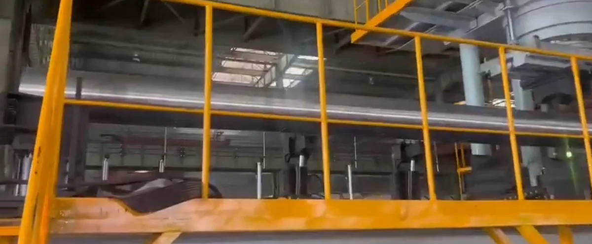
Für lange Teile, Die Durchbiegung des Trägers und die Höhe des Fundaments können die Messung beeinflussen. Die Inbetriebnahme sollte die Unterstützungsausrichtung umfassen, Wiederholbarkeitsprüfungen und ein definiertes Null-/Referenzverfahren vor der Annahme von Produktionsrezepten.
Biegemessung über die gesamte Länge
Das Messsystem kann Laserscanning nutzen, Kontakt-Wegsensoren oder eine andere validierte Methode zur Erfassung des Rohrprofils entlang seiner Länge. Im Messplan muss die Auflösung angegeben werden, Messlänge, Support-Bedingung, Oberflächenhandhabung und ob das Rohr in einer Taktposition gemessen oder gedreht wird, um Biegung und Ovalität in mehreren Ebenen zu trennen.
Wenn der Kunde eine String-Leitung verwendet, Lineal oder Offline-Laserstation, Das Ergebnis der automatischen Maschine sollte mit dieser Methode am gleichen Probensatz verglichen werden. Ziel ist nicht nur die Wiederholgenauigkeit innerhalb der Maschine, aber Zustimmung zur endgültigen Abnahmemethode.
Hydraulische Korrektur mit Abschnittsschutz
Der Controller wählt einen Korrekturpunkt und eine Stützweite basierend auf der gemessenen Biegung. Ein konturierter Pressschuh verteilt die Last auf die Rohroberfläche, während zwei oder mehr Sättel die Reaktionspunkte bilden. Der Hub muss die elastische Auslenkung weit genug überschreiten, um eine kontrollierte dauerhafte Korrektur zu bewirken, aber unter den Grenzwerten bleiben, die sich verschlechtern könnten, das Rohr platt machen oder reißen.
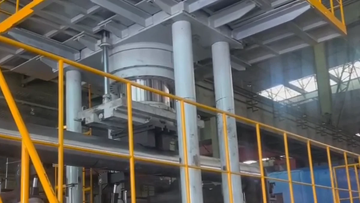
Die Nennkraft kann nicht allein anhand des Außendurchmessers ausgewählt werden. Es hängt von der Wandstärke ab, Stahlsorte und Streckgrenze, Stützspanne, Abschnittsmodul, eingehende Kurve, gewünschtes Restergebnis und zulässige lokale Spannung. Anfängliche Kraft-/Hubgrenzen sollten durch Berechnung und repräsentative Stichprobentests ermittelt werden.
Neumessung, Iterationsgrenzen und NOK-Handhabung
Nach Korrektur, Das Rohr wird unter denselben Auflagebedingungen erneut gemessen. Wenn das Ergebnis außerhalb der Toleranz bleibt, die gemessene Reaktion jedoch normal ist und das Rezept innerhalb seiner validierten Grenzen liegt, Das System berechnet möglicherweise eine weitere Korrektur. Maximaler Hub, Gewalt, Korrekturzählung und Regeln für abnormale Reaktionen verhindern unkontrolliertes wiederholtes Drücken.
Ein Rohr, das das Ziel nicht sicher erreichen kann, sollte als NIO eingestuft oder zur technischen Überprüfung eingeschickt werden. Die Maschine sollte das Vorher/Nachher-Profil beibehalten, Korrekturpositionen, Hübe/Kräfte soweit verfügbar, Rezeptversion und endgültige Entscheidung, wenn die Rückverfolgbarkeit des Projekts dies erfordert.
Empfohlene Zellenkonfiguration
| Modul | Vorgeschlagene Anforderung | Warum es benötigt wird |
|---|---|---|
| Maschinenkonzept | Hochleistungshydraulische Dreipunkt-Rohrrichtpresse | Lokal, kontrollierte Korrektur für große Hohlprofile |
| Werkstückhülle | Außendurchmesser 127–349,25 mm; Wand 9,525–38,1 mm; Länge 1.828,8–12.192 mm | Deckt den angegebenen Projektumfang ab, Vorbehaltlich der Bestätigung des Größenplans |
| Nennkraft / Schlaganfall | Die Dimensionierung erfolgt durch Berechnung und Musterprüfung | Unterdimensionierung verhindern, übermäßiger Stress oder irreführende Modellauswahl |
| Messsystem | Laser-/Kontaktprofilmessung über die gesamte Länge, wie validiert | Unterscheiden Sie zwischen lokaler und allgemeiner Biegung und unterstützen Sie die Korrektur im geschlossenen Regelkreis |
| Unterstützt | Angetriebene/verstellbare Kontursättel mit definierter Höhe und definiertem Abstand | Kontrollieren Sie das Eigengewicht und schützen Sie die Rohroberfläche |
| Positionierung | Angetriebene Rollen, Indexierantrieb oder beweglicher Pressenrahmen | Bringen Sie jede gemessene Biegung sicher zum Korrekturpunkt |
| Werkzeuge | OD-spezifische Pressschuhe und Sättel | Reduzieren Sie das Risiko von Einkerbungen und Ovalität |
| Kontrollen | Größenrezepte, Biegekarte, Korrekturgrenzen und Nachmesslogik | Reduzieren Sie die Abhängigkeit von manueller Beurteilung |
| Handhabung | Kran-/Portal-/Hubbalken-/Rollenschnittstelle mit Anti-Roll-Steuerung | Verwalten Sie einen geschätzten Teilebereich, der mehrere Tonnen umfassen kann |
| Qualitätsdaten | Anfangs-/Endprofil, Korrekturhistorie und OK/NOK-Ergebnis nach Bedarf | Prozessverifizierung und Rückverfolgbarkeit |
| Sicherheit | Bewachung, ineinandergreifende Bewegung, Überlastschutz und sicherer Zugang | Schützen Sie Bediener in der Nähe eines schweren, sich bewegenden runden Werkstücks |
Projektvalidierung vor dem endgültigen Angebot
Die Probenmatrix sollte die kleinsten und größten AD/Wand-Kombinationen abdecken, kürzeste und längste Rohre, normale und ungünstigste Biegungen, alle relevanten Stahlsorten und alle Wärmebehandlungsbedingungen. Bei jedem Versuch sollten Unterstützungspositionen dokumentiert werden, Orientierung, eingehendes Profil, Korrekturposition, Kraft/Hub, sofern verfügbar, endgültiges Profil, Ovalität/Oberflächenzustand und Gesamtzykluszeit.
Bevor das Geradheitsziel zur Maschinengarantie wird, Der Kunde muss bestätigen, ob der erfasste Bedarf besteht 1 mm pro 1000 mm, eine andere Einheit oder ein Gesamtgeradheitsverhältnis. Die Maschinen- und Kundeninspektionsmethoden sollten dann an denselben Proben korreliert werden.
Für einen Vorschlag zur Begradigung nahtloser Rohre erforderliche Informationen
Bitte stellen Sie den vollständigen Rohrleitungsplan zur Verfügung, Materialqualität und Streckgrenze, zertifiziertes oder berechnetes Gewicht, Außendurchmesser und Wandtoleranzen, Verteilung der eingehenden Biegung, lokale und allgemeine Geradheitsanforderungen, Prüfstandard und Messmethode, Ovalitätsgrenze, Oberflächen-/Markierungsbeschränkungen, Support-Bedingung, Zielzykluszeit, Jahresvolumen, Anlagenlayout, Kran-/Walzenschnittstelle und repräsentative Musterrohre.
Mithilfe dieser Eingaben kann das Lösungsteam die Kraft und die Stützspanne berechnen, Wählen Sie das Messprinzip aus, konturierte Werkzeuge entwerfen, Handhabungs- und Sicherheitsanforderungen festlegen, und validieren Sie den Prozess, bevor das endgültige Maschinenmodell und die Nennkraft festgelegt werden.
FAQ
Ist „1 in 1000 mm“ bedeuten einen Zoll Biegung pro 1000 mm?
Es ist mehrdeutig und sollte nicht ohne Bestätigung so interpretiert werden. Es könnte als beabsichtigt gewesen sein 1 mm pro 1000 mm Messlänge. Die Kundenzeichnung oder -spezifikation muss die Einheit definieren, Messlänge, Stützzustand und Prüfmethode.
Kann eine Maschine den Außendurchmesser abdecken? 127 Zu 349.25 mm und Längen bis zu 12.2 M?
Potenziell, aber der Kraftbereich, Pressweg, Unterstützungspositionen, Messfeld, Werkzeugwechsel und Handhabungssystem müssen den gesamten Größenplan abdecken. Es ist eine Liste der tatsächlichen Kombinationen aus Außendurchmesser, Wand und Länge erforderlich; Reichweitenendpunkte allein reichen nicht aus.
Wie wird das Abflachen von Rohren beim Pressrichten verhindert??
Die Lösung verwendet konturierte Pressschuhe und Sättel, kontrollierte Stützspanne und validierte Kraft-/Weggrenzen. Ovalität und Oberflächenzustand sollten in den Abnahmeplan für die Probenprüfung einbezogen werden, wenn es sich um funktionelle Anforderungen handelt.
How does the machine compensate for the pipe's own weight?
Das Rohr wird unter einem definierten Wert vermessen, wiederholbare Unterstützungsbedingung. Stützpositionen und -höhen sind in jedem Rezept enthalten, and the machine result is correlated with the customer's final inspection method.
Ist die erforderliche Maschinentonnage bereits bestätigt??
NEIN. Die Nennkraft muss aus der Materialgüte berechnet werden, Streckgrenze, Abschnitt, Stützweite und eingehende Biegung, anschließend mit repräsentativen Proben validiert. Auf dieser Seite wird absichtlich kein ungeprüftes Modell oder eine ungeprüfte Tonnage angegeben.
Kann das System einen erfahrenen manuellen Richtarbeiter ersetzen??
Es kann die Messung standardisieren, Auswahl der Biegestelle, Korrekturgrenzen, Nachmessung und Aufzeichnungen. Für die Materialversorgung werden weiterhin Bediener benötigt, Werkzeugprüfungen, Inspektionsaudits, Wartung und abnormale Leitungen, es sei denn, die gesamte Zelle ist für ein anderes Personalmodell ausgelegt.
Was ist vor dem Angebot erforderlich??
Das minimale nützliche Paket ist der Rohrplan, Grad, Gewicht, eingehende Kurve, lokales/gesamtes Ziel, Inspektionsmethode, Ovalität/Oberflächengrenzen, Produktionsziel, Anlagenlayout und Musterrohre.
Abschluss
Das Richten großer nahtloser Rohre ist eine kombinierte Messtechnik, Strukturkorrektur und Materialhandhabungsproblem. Das Endergebnis hängt von der Kontrolle des Eigengewichts ab, Abbildung der gesamten Biegung, Verteilen des Presskontakts über das Hohlprofil und Wiederholen der Messung unter denselben Auflagebedingungen.
Die Technik auf dieser Seite ist nur das halbe Bild – Die Vergleich zwischen manuellem und automatischem Richten und die ROI-Arbeitsblatt zum automatischen Richten decken die kommerzielle Hälfte eines Projekts für nahtlose Stahlrohre ab.
Senden Sie Ihren Rohrplan, Stahlsorte, eingehendes Biegeprofil, Geradheitsdefinition, Produktionsziel und Musterinformationen für eine Machbarkeitsprüfung. Die finale Presskraft, Werkzeuge, unterstützt, Das Messsystem und das Maschinenmodell sollten durch technische Berechnungen und repräsentative Musterversuche bestätigt werden.