
Beton- und Bohrhammerbohrer kombinieren einen langen Stahlkörper mit spiralförmigen Nuten, eine Hartmetall-Schneidstruktur und einen geschlitzten oder profilierten Antriebsschaft. Durch diese Merkmale unterscheidet sich das Werkstück deutlich von einem einfachen Rundstab. Eine Messsonde kann der Flöte statt der wahren Körperachse folgen, während eine falsch platzierte Stütze oder Presse die Hartmetallverbindung beschädigen kann, Schneidkopf, Nutenkante oder SDS-Anschluss.
Eine Lösung zum Richten von Betonbohrern muss daher genau auf die Bohrerfamilie und das Herstellungsstadium zugeschnitten sein. Es sollte ein zeichnungsdefiniertes Merkmal messen, Korrigieren Sie nur genehmigte Stahlbereiche und überprüfen Sie nach der Korrektur sowohl die Geometrie als auch den Zustand.
Betonbohrer sind kein einheitliches Werkstück
Offizielle Produktsortimente weisen erhebliche Konstruktionsunterschiede auf. Bosch listet Zweischneider-Wolframkarbidplatten auf, Vierschneider-Vollhartmetallköpfe, zwei- und vierflötenige Korpusse, spezielle geschweißte Spitzenverbindungen und SDS Plus-Schäfte. Hilti listet Vollhartmetall-Mehrschneiderköpfe und Vierfachwendel auf. DEWALT listet Hartmetallspitzen auf, offene Designs und längliche vierschneidige Körper.

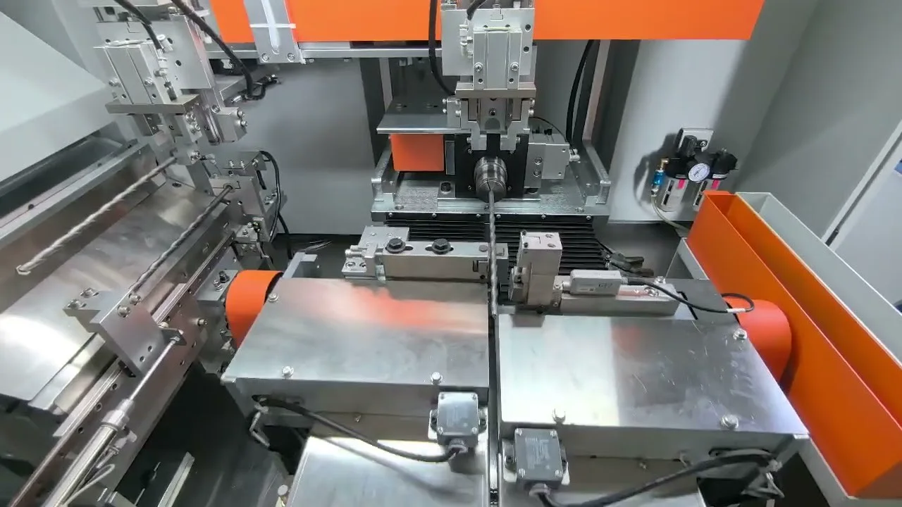
Das Bild ist ein echtes Miniaturbild aus dem Elektro-Hammerbohrer-Video des Projekts. Es handelt sich um einen geriffelten Bohrer, Haltestation und Korrekturmechanismus. Es wird kein Bitmaterial hergestellt, Abmessungen, Genauigkeit oder Zykluszeit.
| Werkstückmerkmal | Richtende Konsequenz |
|---|---|
| Gelötete/geschweißte Hartmetallplatte | Gelenk und Hartmetall müssen normalerweise außerhalb der Press-/Stützzone bleiben |
| Vollhartmetall-Mehrschneiderkopf | Ein höherwertiger spröder Kopf erfordert eine kontrollierte Handhabung und einen Aufprallschutz |
| Zwei- oder vierschneidige Spirale | Die Kontaktmessung ändert sich mit der axialen und Winkelposition |
| Reduzierter Kern oder unterschiedliche Nuttiefe | Die Biegesteifigkeit ändert sich entlang der Arbeitslänge |
| SDS Plus/Max oder anderer Antriebsschaft | Schlitze und Antriebsmerkmale sind keine einfachen zylindrischen Bezugspunkte |
| Runden, flaches oder proprietäres Spannfutterende | Erfordert eine variantenspezifische Locator- und Runout-Definition |
| Gehäuse aus gehärtetem oder oberflächenbehandeltem Stahl | Ändert die Rückfederung, Gefahr von Markierungen und Rissen |
Identifizieren Sie die Fertigungsphase
| Bühne | Möglicher Zweck | Hauptbeschränkung |
|---|---|---|
| Stahlrohling vor dem Riffeln | Stellen Sie vor der Bearbeitung/Umformung einen geraden Bezug her | Die endgültige Beziehung zwischen Flöte und Kopf liegt noch nicht vor |
| Nach dem Formen der Hohlkehle | Korrigieren Sie die Körperverformung, bevor Sie das Hartmetall anbringen | Messung durch ein periodisches Spiralprofil |
| Nach der Wärmebehandlung | Korrigieren Sie die thermische Verformung | Härte, Rückfederungs- und Rissgrenzen erfordern eine Validierung |
| Nach Hartmetallbefestigung | Korrekter Zusammenbau bzw. Fügeverzug | Schützen Sie Hartmetall und Löt-/Schweißverbindungen |
| Nach dem Schleifen/Beschichten | Treffen Sie die endgültige Geometrie | Sehr strenger Oberflächen- und Kantenschutz |
Die sicherste und leistungsfähigste Stufe ist nicht automatisch die letzte. Wenn ein Prozess nach einer früheren Korrektur wiederholt Bits verbiegt, Das Projekt sollte sich mit dieser vorgelagerten Ursache befassen oder den Richtvorgang in die entsprechende spätere Phase verschieben.
Erforderliche Projekteingaben
| Eingang | Erforderliche Angaben |
|---|---|
| Zeichnung | Revision, kontrollierte Funktion, Datum und Toleranzen |
| Etwas Familie | Durchmesser, Gesamt-/Arbeitslänge, Anzahl der Nuten und Kernprofil |
| Schneidkopf | Hartmetallplatte/Vollkopf, Anzahl der Fräser, Gelenktyp und verbotene Zonen |
| Schaft | SDS Plus/Max, runden, Hex- oder proprietäre Verbindungsgeometrie |
| Materialweg | Stahlsorte, Härten, Hartmetallbefestigung und Beschichtungssequenz |
| Eingehende Kurve | Größe, ebene und axiale Verteilung aus repräsentativen Chargen |
| Endkontrolle | Geradheits-/Rundlauf-/Profilmethode, Messgerät, Orientierung und Auflösung |
| Produktionsumfang | Varianten, Ausgabeziel, Laden, Umstellung und Rückverfolgbarkeit |
Die vorherigen Seiten enthielten keine verifizierte Größe, Härte, Genauigkeit oder Zyklusdaten. Aus dem Video sollte nichts abgeleitet werden.
Geradlinigkeit, Rundlauf und Spitzenausrichtung sind unterschiedlich
| Merkmal | Was es bewertet | Definition erforderlich |
|---|---|---|
| Körpergeradheit | Form eines ausgewählten Flächenelements oder einer abgeleiteten Körperachse | Kontrollierte Länge und flötenbewusste Bewertungsmethode |
| Radialer Runout | Oberflächenvariation beim Drehen um einen Bezugspunkt | Datumsmerkmale, Sonde/optische Position und Winkelabtastung |
| Ausrichtung von Spitze zu Schaft | Zusammenhang zwischen Schneidkopf und Antriebsschaftachse | Kopfmerkmal, Schaftbezugspunkt und Akzeptanzzone |
| Flötenprofil/Führung | Spiralförmige Feature-Geometrie | Axialer Bereich, Winkelreferenz- und Profilmethode |
| Funktionelle Rotation | Verhalten in einem zugelassenen Spannfutter oder einer Prüfspindel | Futter, Einstecktiefe, Geschwindigkeit und gemessener Standort |
ISO 1101 definiert die Sprache für die geometrische Spezifikation, Die Kundenzeichnung muss jedoch das tatsächlich tolerierte Merkmal angeben. Eine Maschine kann „Geradheit oder Rundlaufgenauigkeit nicht gewährleisten“, solange diese Wahl und dieser Bezugspunkt nicht explizit festgelegt sind.
Flötenbewusstes Messen ist unerlässlich
Eine Kontaktsonde, die eine rotierende Spirale berührt, steigt und senkt sich mit der Rille. Dieses periodische Signal kann viel größer sein als die ausgewertete Mittellinienbiegung. SDS-Steckplätze und -Abflachungen verursachen das gleiche Problem auf der Laufwerksseite.
Das Messkonzept sollte eines oder mehrere der folgenden Elemente verwenden:
- eine definierte glatte zylindrische Fläche, wenn die Zeichnung eine solche vorsieht;
- kontrollierte Winkelindizierung zur Messung der gleichen Nut-Steg-Beziehung;
- mehrere optische Silhouetten und ein kalibriertes Mittellinien-/Profilmodell;
- ein berührungsloser Sensor an zugelassenen axialen Positionen;
- ein Master-Spannfutter oder Zentrierspitzen, die den Funktionsbezug darstellen;
- Filterung, die anhand bekannter Referenzteile validiert wurde, nicht ausgewählt, nur um das Diagramm glatt aussehen zu lassen.
Sondenkraft, Auflageposition und Spannkraft müssen zudem so niedrig sein, dass der schlanke Bohrerkörper durch die Messung selbst nicht verbogen wird.
Empfohlener Richtprozess mit geschlossenem Regelkreis
1. Identifizieren Sie die Bitfamilie
Der Bediener oder die Automatisierung überprüft den Bohrerdurchmesser, Länge, Nut-/Kopfdesign und Schafttyp. Das Rezept wählt den Locator aus, unterstützt, zugelassene Messpositionen, Korrekturgrenzen und Sperrzonen.
2. Laden, ohne die Schneidkanten zu berühren
Tablett, Magazin- oder Feeder-Werkzeuge liefern einen Bohrer, ohne dass Hartmetall gegen Hartmetall schlägt. Der Kopf und die Flötenkanten bleiben frei von harten Anschlägen. Die automatische Zuführung muss mit realer Länge getestet werden, Oberfläche, Öl- und Verschränkungsbedingungen.
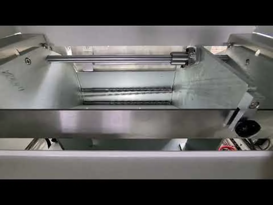
Dieser Rahmen stammt aus dem richtigen öffentlichen Video zur Betonbohrmaschine und zeigt den Einzugsbereich. Es ist kein Beweis für die unbeaufsichtigte Fütterungsleistung, Kapazität oder Umrüstzeit.
3. Legen Sie den Bezug fest
Der Bohrer wird von einer bewährten glatten Schaftzone gehalten, Zentren oder eine funktionale Schnittstelle. SDS-Slots werden indiziert, wenn sie den Locator beeinflussen. Die Vorrichtung darf den Bohrer nicht künstlich gerade halten.
4. Messen Sie die eingehende Geometrie
Kontakt- oder berührungslose Sensoren erfassen Daten nur an validierten Positionen und Ausrichtungen. Die Steuerung trennt die wiederholbare Wellen-/Profilsignatur von der Biegecharakteristik und speichert das eingehende Ergebnis.
5. Stützen und Korrekturpunkt auswählen
Stützen und Pressen wirken auf zugelassene Stahlkörperzonen. Der Schneidkopf, Hartmetallgelenk, Flötenkante, reduzierter Kern, Wärmebehandlungsübergangs- und SDB-Merkmale sind ausgeschlossen, es sei denn, die Zeichnung und die Musterprüfung genehmigen den Kontakt ausdrücklich.
6. Wenden Sie eine begrenzte Punktkorrektur an
Die Presse übt eine kontrollierte Verschiebung oder Kraft aus. Gehärtet, Schlanke und geriffelte Bits erfordern eine stufenweise Korrektur mit maximaler Kraft/Hub und Iterationsgrenzen. Eine starke Korrektur ist keine allgemeine Strategie.
7. Unter Verwendung des gleichen Bezugspunkts erneut messen
Das Teil wird erneut gemessen, ohne dass die Bezugslogik geändert wird. Eine weitere Korrektur ist nur innerhalb des validierten Fensters zulässig. Teile mit übermäßiger Eingangsbiegung, Instabile Messwerte oder unerwartete Rückfederungen werden zur Überprüfung getrennt.
8. Zustand und Funktion prüfen
Endkontrollen können die Geometrie umfassen, Karbid-/Verbindungsinspektion, Zustand der Flöte und Beschichtung, Rissprüfung und funktionsfähige Futterrotation. Der erforderliche Satz richtet sich nach der Fertigungsstufe und dem Qualitätsplan.
Video zum Richten von echten Betonbohrern
Das folgende Video trägt den Titel Automatic Straightening Machine for concrete bit auf dem Kanal Richtmaschine. Es zeigt eine Beton-/Bohrhammerbohrzelle mit Zuführung, Halte- und Korrekturgeräte. Es beweist keine besondere Genauigkeit, Ausgabe, Ertrag oder Kundenergebnis.
Oberfläche, Hartmetall- und Gelenkschutz
| Risiko | Kontrolle |
|---|---|
| Hartmetallspitze durch Handhabung abgeplatzt | Trennen Sie die Teile und verwenden Sie Werkzeuge zur Kopffreigabe |
| Löt-/Schweißverbindung überlastet | Definieren Sie einen Ausschlussabstand und ein maximales Korrekturmoment |
| Flötenkante verbeult | Nutzen Sie profilgerechte Stützen und zugelassene Kontaktzonen |
| Risse im verhärteten Körper | Begrenzen Sie eingehende Biegungen und Korrekturen; Fügen Sie die erforderliche Rissprüfung hinzu |
| SDS-Steckplatz als falsches Datum verwendet | Auf zeichnungsgenehmigten Oberflächen oder einer funktionalen Spannfutterschnittstelle anordnen |
| Sonde folgt Helix | Verwenden Sie indexierte/profilbewusste oder berührungslose Messungen |
| Beschichtung oder Finish markiert | Kontaktmaterial validieren, Druck- und Inspektionsnorm |
| Bit springt aus der Halterung | Kontrollieren Sie die Klemmung und schützen Sie den Korrekturbereich |
Punktkorrektur oder Rollenrichten?
| Entscheidungsfaktor | Eine Punktkorrektur kann bevorzugt sein, wenn | Das Richten durch Rollen kann bewertet werden, wenn |
|---|---|---|
| Biegeverteilung | Höhepunkte können individuell gemessen werden | Die Krümmung ist entlang eines ausreichend gleichmäßigen Körpers verteilt |
| Geometrie | Kopf, Nuten und Schaft erfordern einen selektiven Kontakt | Es steht eine durchgehende Rollenkontaktbahn zur Verfügung |
| Messung | Eine erneute Messung im geschlossenen Regelkreis ist erforderlich | Vorher/Nachher-Inline-Messungen können das Ergebnis überprüfen |
| Oberfläche | Lokaler geschützter Kontakt ist akzeptabel | Ständiger Rollenkontakt ist zulässig |
| Produktmix | Mehrere Varianten erfordern spezielle Rezepte/Werkzeuge | Stabile Familien mit höherem Volumen teilen sich einen validierten Rollenaufbau |
Der Hartmetallkopf verhindert nicht automatisch jegliches Richten, aber es verengt das sichere Kontakt- und Korrekturfenster. Der Prozess wird anhand von Mustern und der Zeichnung ausgewählt, nicht von einem universellen Slogan.
Mustertest- und Abnahmeplan
Repräsentative Beispiele
- kleinster Körper/Kern und längste flexible Variante;
- jede Flöte zählt, Hartmetallkopfdesign und Schaftfamilie;
- jede Wärmebehandlungs- und Beschichtungsbedingung;
- Proben über die tatsächliche Eingangsbiegungsverteilung;
- Mehrere Produktionschargen, bei denen Verbindungsverzug oder Rückfederung variieren können;
- Randteile in der Nähe der vorgesehenen Korrekturgrenze.
Erforderliche Nachweise
| Aufzeichnen | Akzeptanzbeweis |
|---|---|
| Teileidentität | Zeichnungsüberarbeitung, Variante, Materialweg und Charge |
| Eingehende Geometrie | Datum, Orientierung, Positionen und Messwerte |
| Werkzeuge | Locator, unterstützt, Presse- und Kontaktverbotszonen |
| Korrekturverlauf | Standort, Kraft/Weg und Anzahl der Iterationen |
| Endgültige Geometrie | Gleicher Maschinenaufbau plus Kunden-Messwert-Korrelation |
| Zustand von Kopf/Gelenk/Flöte | Einverstanden visuell, vergrößertes oder NDT-Ergebnis |
| Funktionelles Ergebnis | Bei Bedarf Drehfutterdrehung oder nachgeschalteter Test |
| Produktionsversuch | Gemessener Zyklus, Fütterungsstabilität, Umstellung und Verfügbarkeit |
Automatisierung und Umstellung
| Ebene | Typischer Umfang |
|---|---|
| Manuelles Laden | Bediener lädt; Maschinenmaße, korrigiert und überprüft |
| Magazin/Tablett | Kontrollierte Präsentation für eine stabile Bit-Familie |
| Automatische Zelle | Füttern, Identifikation, Messung, Korrektur und Sortierung |
| Rückverfolgbare Zelle | Teil/Los, Rezept, Mess- und Korrekturaufzeichnungen |
Für eine Änderung des Durchmessers oder der Länge sind möglicherweise Stützen erforderlich, Futter, Sensorposition und Presswerkzeugänderungen. Der Wechsel von einem SDS Plus-Bohrer mit zwei Schneiden zu einem Vollhartmetall-Vierschneider oder einer anderen Schaftfamilie ist nicht nur eine Änderung des SPS-Rezepts.
Was kein universelles Versprechen ist
Vor der Zeichnungsprüfung und Probenvalidierung, Diese Lösung verspricht nichts:
- eine Toleranz, Zykluszeit oder Ausbeute für jeden Betonbohrer;
- dass Geradheit und Rundlauf austauschbar sind;
- Korrektur jeder eingehenden Biegegröße;
- Keine Schädigung des Hartmetalls, gemeinsam, Flöte, Beschichtung oder Schaft;
- Automatische Zuführung für jede Länge und jeden Kopfstil;
- dass die SPS-Steuerung Software überflüssig macht, Werkzeug- oder Umrüstarbeiten;
- eine feste Arbeitsersparnis oder Produktionsverbesserung;
- sichere Reparatur von Gebrauchten, durch Stöße beschädigte oder gerissene Bohrer.
Verwandte Anwendungen
Rezension Lösungen zum Richten von Verbindungselementen und Werkzeugen und die Richtmaschine für Kugelzapfen für angrenzende Werkzeug- und Korrekturkonzepte. Medizinische und chirurgische Bohrer bleiben aufgrund ihres Werkstücks eine separate Inhaltsfamilie, Oberfläche, Die regulatorischen und messtechnischen Anforderungen sind unterschiedlich.
Für ein Angebot einzusendende Informationen
Diese Betonbohrer-Anleitung in eine Kaufentscheidung umzuwandeln, Beginnen Sie mit dem Komplettlösung zur Auswahl eines Glätteisens und testen Sie die Zahlen mit dem Druck Budgetbild für eine Richtmaschine.
Senden Sie die Zeichnung und die Überarbeitung, repräsentative Proben, Durchmesser/Länge/Nut/Kopf/Schaftbereich, Material und Härteweg, Hartmetall-Befestigungsmethode, Herstellungsphase, Eingangsbogenverteilung, endgültiges Merkmal und Datum, Einrichtung der Kundeninspektion, verbotene Kontaktzonen, Regeln zur Kopf-/Verbindungs-/Flöteninspektion, Ausgabeziel und Ladepräferenz.
Kontaktieren Sie StraighteningTech für eine probenbasierte Richtstudie für Betonbohrer. Wir definieren das Messmodell, geschütztes Werkzeug, Korrekturgrenzen, Automatisierungsumfang und Akzeptanznachweis für die aktuelle Bitfamilie.
Häufig gestellte Fragen
Kann die Sonde direkt auf einer Spiralnut messen??
Nur mit einer Methode, die für dieses Profil entwickelt wurde. Andernfalls folgt eine rotierende Kontaktsonde der Helix und kann eine periodische Profiländerung mit einer Mittellinienbiegung verwechseln. Verwenden Sie eine kontrollierte Indizierung, ein validiertes Profilmodell, eine glatte Fläche oder eine geeignete berührungslose Messung.
Kann der Hartmetallkopf als Stütz- oder Presspunkt verwendet werden??
Nicht standardmäßig. Hartmetall und seine Löt-/Schweißverbindung sind sensible Funktionszonen. Das Werkzeug wirkt normalerweise auf zugelassene Stahlkörperbereiche mit einem Ausschlussabstand von Kopf und Gelenk.
Ist ein SDS-Schaft ein zuverlässiges Rotationsdatum??
Nur wenn die Zeichnung oder Funktionsprüfung dies so definiert und der Locator die freigegebene Spannfutterschnittstelle nachbildet. Seine Schlitze und Antriebsmerkmale entsprechen nicht einer vollständig zylindrischen Oberfläche.
Soll der Bohrer vor oder nach der Hartmetallbefestigung gerichtet werden??
Das hängt davon ab, wo die Verzerrung eingeführt wird und welche endgültige Beziehung kontrolliert wird. Ein früheres Richten bietet einen sichereren Kontakt; Durch späteres Richten können Verbindungs- oder Wärmebehandlungsverzerrungen korrigiert werden, es sind jedoch strengere Schutz- und Korrekturgrenzen erforderlich.
Kann ein Rezept zwei abdecken?- und Vierschneider-Bits?
Nicht automatisch. Kopffreiheit, Flötensignatur, Steifheit, Datum, Stütz- und Sensorpositionen können unterschiedlich sein. Jede validierte Familie benötigt die richtige Werkzeug- und Rezeptkombination.
Technische Referenzgrenze
- Bosch SDS plus-1: https://www.bosch-professional.com/mz/de/sds-plus-1-hammerbohrer-2868938-ocs-ac/
- Bosch EXPERT SDS plus-7X: https://www.bosch-professional.com/de/de/expert-sds-plus-7x-hammerbohrer-2867204-ocs-ac/
- Bosch SDS plus-3: https://www.bosch-professional.com/in/en/sds-plus-3-hammer-drill-bits-2867846-ocs-ac/
- Hilti TE-CX: https://www.hilti.com/c/CLS_POWER_TOOL_INSERT_7126/CLS_CONCRETE_MASONRY_DRILL_BITS_7126/r4429
- DEWALT SDS Plus Steinbohrer: https://www.dewalt.com/en-us/product/dw5443/916-x-10-x-12-rock-carbide-sds-plus-drill-bit
- MAE Werkstücke und Anwendungen: https://mae-group.com/de/werkstücke-anwendungen/
- ISO 1101:2017: https://www.iso.org/standard/66777.html
Diese Referenzen unterstützen die Vielfalt der Bohrerkonstruktionen und allgemeine Geometrie-/Richtprinzipien. Sie beweisen nicht, dass die Leistung eines anderen Anbieters für eine StraighteningTech-Konfiguration gilt.