
Pistolboring og opretning af dybhulsbor er et specialiseret problem i fremstillingsfasen. En boremaskine er ikke en almindelig rund aksel: skaftet, fløjte, skærehoved, kølevæske funktioner, varmebehandlingstilstand og senere slibe- eller genslibeoperationer kan hver især ændre sig, hvor værktøjet kan understøttes, målt og korrigeret. En proces, der kun får værktøjet til at se lige ud, kan stadig beskadige en beskyttet funktion eller bruge et datum, der ikke repræsenterer funktionel inspektion.
Denne artikel giver en prøve-testramme, ikke et løfte om, at StraighteningTech understøtter enhver borgeometri eller størrelse. Den endelige proces afhænger af tegningen, repræsentative værktøjer, materiel tilstand, permitted contact zones and the customer's released-state inspection method.

*Engineering koncept illustration. Det viser en kandidat lang-værktøj korrektion kontekst; det er ikke en kundedatablad eller bevis for et garanteret boreresultat.*
Definer værktøjsfamilien og udelad Look-Alike-hensigter
Den nøjagtige forespørgsel frembringer et specialistudretningsresultat for dyb-hulsbor, men også boremaskine, genslibning, resultater med pistolløb og generelle hydrauliske glattejern. Det er separate hensigter. Omfanget her er en pistolbor i fremstillingsfasen eller dybhulsbor, hvis geometri skal evalueres før den næste godkendte operation.
| Omfatte | Udelukke |
|---|---|
| Retheds- eller runout-evaluering af en kontrolleret borefamilie | Valg af dybhulsboremaskine |
| Skaft, fløjte- og hovedbeskyttelse under et kandidatkorrektionsforsøg | Omslibning, slibning eller boring |
| Prøvebaseret datum og frigivet inspektionsplanlægning | Pistolløb, betonbor og medicinske borekrav |
Artiklen skal linke til det eksisterende boreværktøj udretningsomfang men ikke stille og roligt behandle det brede nav som et bevis på, at hver pistoløvelse allerede er dækket.
Spor forvrængning til fremstillingsfasen
Værktøjsgeometri kan blive påvirket af råmaterialets tilstand, bearbejdning, fløjtedannelse, varmebehandling, overfladebehandling, håndtering eller et tidligere rettelsesforsøg. Timingen ændrer den tilladte kontaktstrategi. Et emne, der senere vil blive slibet, kan gennemgås anderledes end et færdigt bor med beskyttede skærefunktioner.
Før en retssag, identificere den kontrollerede værktøjstegning, materiale og varmebehandlingstilstand, længde og skiftende diameter, skaft/endegeometri, fløjte/hoved funktioner, nuværende produktionsstadie, indgående afvigelseskort og næste proces. Kopier ikke konkurrentens dimensioner, antal akser, kraft, cyklustid eller automatiseringskrav til en lokal specifikation.
Why Deep-Hole Tools Distort the Way They Do
A gun drill earns its distortion. The raw drill rod is already extremely slender — length-to-diameter ratios that would embarrass a transmission shaft — and then the manufacturing route removes material asymmetrically: fluting or milling a chip channel along one side, cutting the driver flat, adding the head with its cutting geometry and coolant passage. Every one of those operations removes constraint from where it was and leaves residual stress where machining worked the material. Heat treatment then adds its signature on the now-asymmetric section, and deep-hole drilling the coolant bore through the core disturbs the stress balance a second time. The finished tool is a precision instrument carrying several overlaid distortion fields. Understanding this stack is practical, not academic: it predicts that bends concentrate near section transitions — head to flute, flute to shank — that the same tool design can distort differently across lots, and that a correction process which treats the tool as a plain bar will both measure and press in the wrong places. The staging logic and its interaction with correction are the same covered for glatning efter varmebehandling, applied to a section that never had symmetry to begin with.
The Asymmetry Problem: Fluted Sections Are Not Shafts
On the fluted length, the cross-section is an open profile with a neutral axis displaced away from the geometric center — the material web and the chip channel do not balance. Two engineering consequences follow. Stiffness becomes directional: the section bends more easily in the plane of the flute than perpendicular to it, so the same correction stroke delivered at the same force produces different movement depending on the tool’s clocking — the correction plan must therefore be orientation-aware, not just position-aware. And measurement on the flute reads a surface that is spiraling: a probe tracking the OD of a fluted tool sees the flute pass as an interruption, and the residual OD between flutes follows a helix, so naive readings mix the helix geometry into the axis map. The disciplined answers are angular masking — read only in defined rotational windows between flutes — and separating the shank, where the section is solid and behaves classically, from the fluted length, where every number needs its context. The same interrupted-surface caution applies to the rock-drill and heavy-tool families covered under heat-treated drill rod straightening.
Vælg et funktionelt dato- og målekort
Ligehed, radial udløb og skærehoved forhold er ikke udskiftelige. Det skal fremgå af kundetegningen, hvilken egenskab der styrer accept, og hvordan værktøjet understøttes eller roteres. En skaft kan kun være en kandidatreference, hvis den matcher den nødvendige funktionsakse, og dens tilstand er kontrolleret.
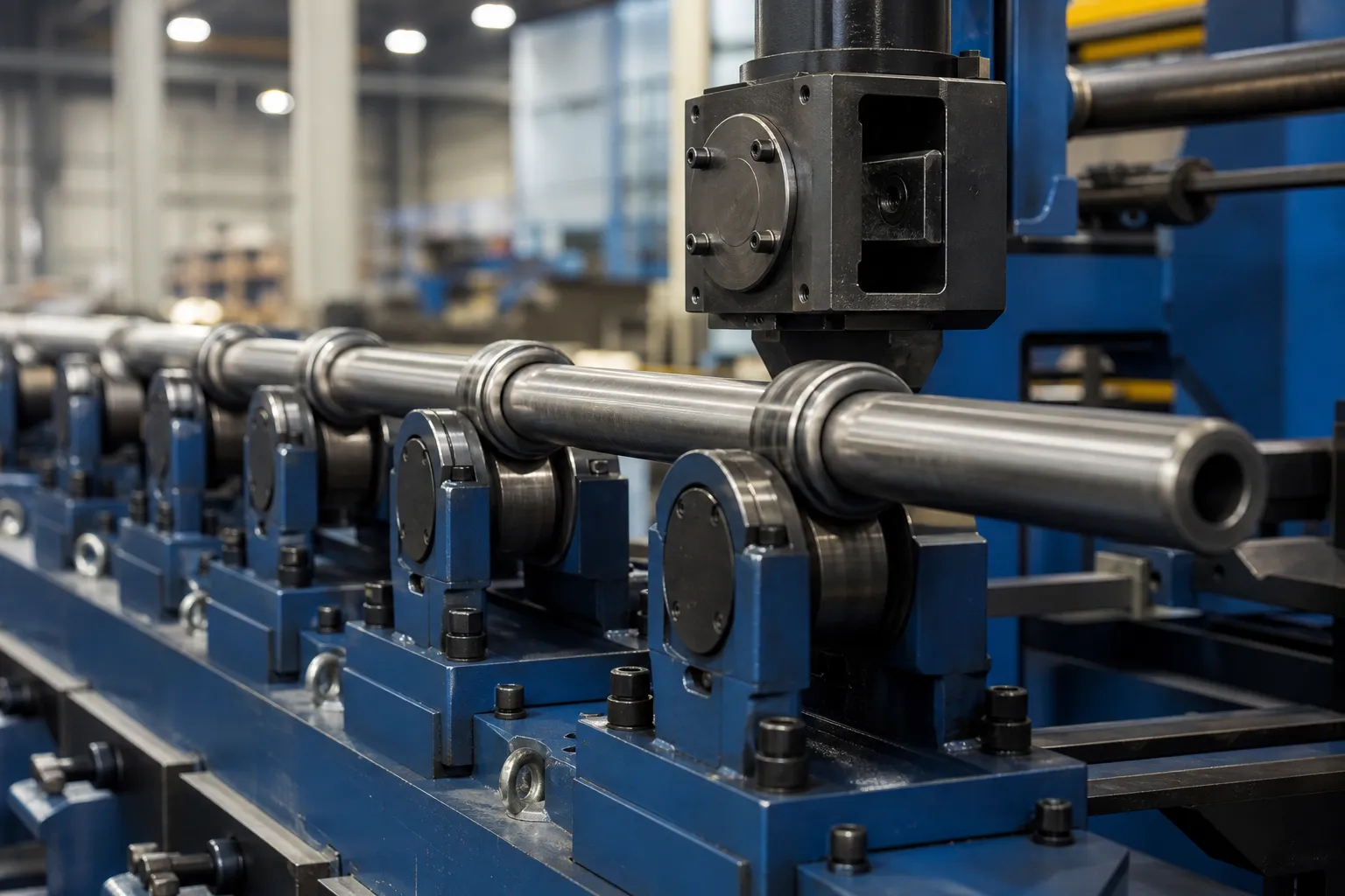
*Engineering koncept illustration. Det understreger, at lange slanke værktøjer har brug for støtteplanlægning; det nøjagtige antal stationer og registreringsmetoden skal valideres fra borefamilien.*
Målegennemgangen bør registrere godkendte referencefunktioner, aksiale stationer, rotationsmetode, hvis den anvendes, sondekontaktbetingelser, vinkelmasker til fløjter eller huller, supportsteder og den frigivne tilstand brugt til endelig accept. En lokal funktion eller ikke-understøttet spændvidde kan ellers forveksles med en hel-værktøjsbøjning.
Beskyt skaftet, Fløjte og skærehoved
Støtte- og korrektionsplaceringer skal godkendes fra geometrikortet og gennemgangen af beskyttet zone. Fløjter, skærekanter, kølevæske huller, coatede zoner og lokale ændringer i snit kan skabe både kontaktrisiko og vildledende måling. En tilgængelig overflade er ikke automatisk et acceptabelt belastningspunkt.
| Zone | Teknisk spørgsmål |
|---|---|
| Skaft | Fastlægger det det funktionelle datum og tolererer det den foreslåede støtte? |
| Fløjte | Kan sonde eller støttekontakt undgå afbrudt overfladesignal og mærkning? |
| Skærehoved | Er kontakt forbudt, fordi det kan påvirke kantgeometri eller efterfølgende efterbehandling? |
| Slank spændvidde | Understøtter mellemrum forhindrer nedbøjning i at blive et tilsyneladende korrektionsmål? |
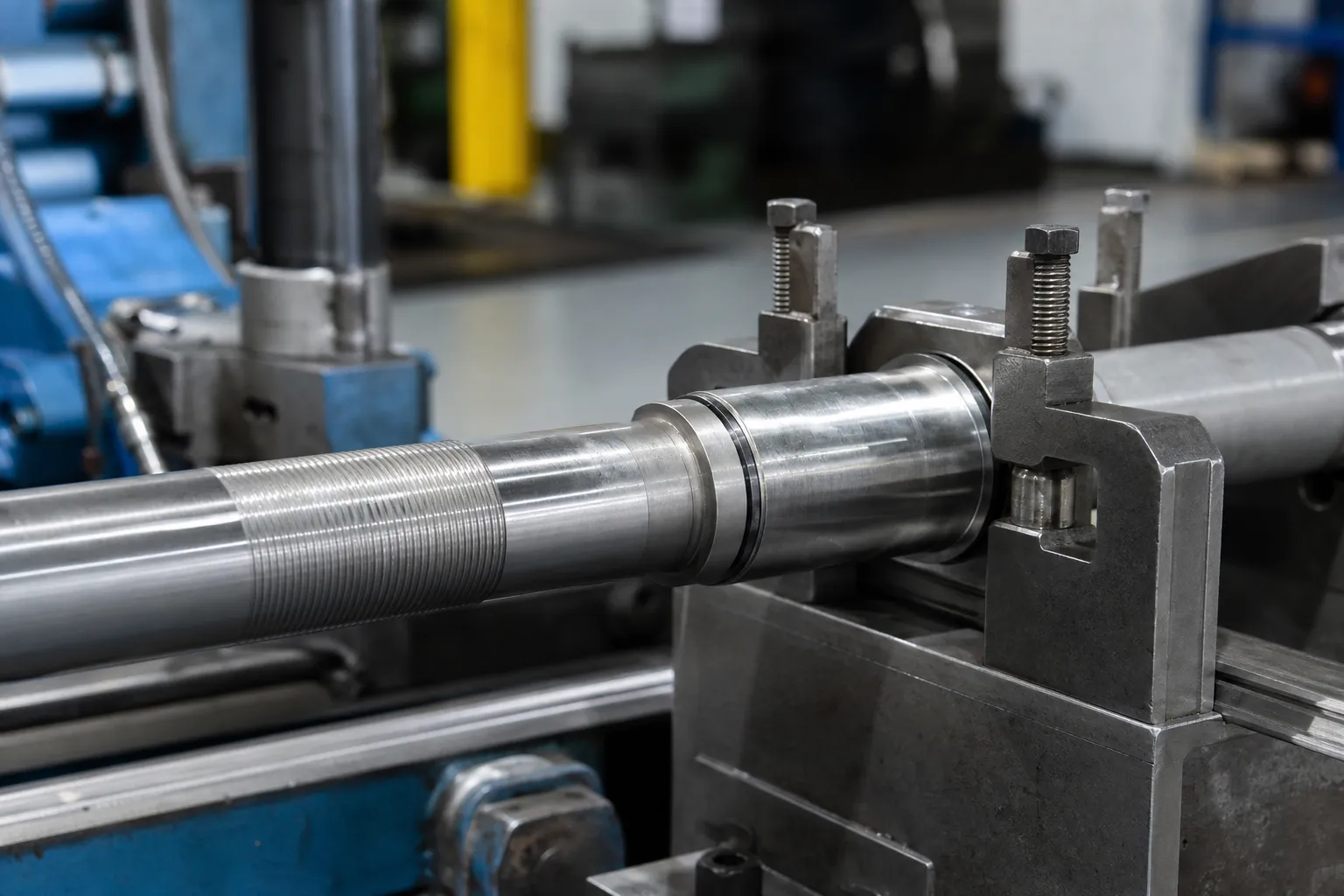
*Engineering koncept illustration. Det viser et inkrementelt korrektionskoncept, ikke et godkendt tryk, slagtilfælde, armatur eller produktionsopskrift.*
Where Straightening Sits in the Tool’s Process Route
The same tool asks a different straightening question depending on where it stands in its route. A blank or semi-finished rod, heading into grinding, offers contact freedom — surfaces that will be removed anyway tolerate correction marks that a finished tool cannot — and its acceptance question is whether the grinding allowance can clean up the corrected geometry. A finished drill, flutes cut and edges prepared, inverts every priority: protected zones dominate, corrections must land on the plain spans, and the acceptance question is functional runout on the customer’s own inspection. A reground tool arrives with its straightness history already spent once and its dimensions changed from nominal, so the correction recipe it ran under as a new tool no longer describes it — the rework rules and deformation budget from the rework-limit framework apply with full force. Freezing the manufacturing stage in the trial record, as the framework above requires, is what keeps these three conversations from blurring into one expensive misunderstanding.
Handling Interrupted Surfaces in the Measurement
Practical measurement plans for fluted tools converge on a small set of techniques, each with a cost. Angular masking — sampling only in the windows between flute passes — keeps the probe on continuous material at the price of fewer readings per revolution and a defined rotational reference to keep the windows aligned between stations. Shank-based mapping — measuring the solid sections precisely and interpolating across the fluted span — gives clean numbers at the ends but assumes the fluted length behaves smoothly between them, an assumption the distortion physics occasionally betrays near the head. Feature-aware fixturing — supporting on the land between flutes with conformal tooling — preserves the tool’s attitude but makes support condition part of the measurement definition, to be held identical between the machine and any verification station, per the datum discipline in trindelt akselmåling datumvalg. Whichever combination a process adopts, the rule that decides its credibility is unchanged: reseat and repeat, and treat any peak that fails the reseat check as a hypothesis rather than a correction target.
Use an Incremental, Released-State Correction Loop
- verify the approved drill family, manufacturing stage and incoming condition;
- efterse for skader, out-of-scope deformation or prohibited surface condition;
- establish and verify the datum and support setup;
- map the agreed geometry before correction;
- select only approved supports and correction points;
- apply an incremental correction within the sample-test limit;
- fully release the tool and restraint;
- remeasure and record OK, NOK or engineering-review disposition.
The final decision must follow release. A reading while a tool is clamped or under force cannot be presented as final straightness or runout.
Build Acceptance Around Representative Tools
The sample package should include normal and worst-case incoming drills, the controlled drawing, reference gauge, måle korrelation, inspektion af beskyttet overflade og en eksplicit grænse for ingen fremskridt. Hvor revner eller materialeintegritet gør sig gældende, formel NDT forbliver en separat proces, medmindre den ansvarlige metode er specificeret og kvalificeret; korrektionsovervågning erstatter den ikke automatisk.
For den bredere accept arbejdsgang, se udretning prøve test og accept og akslens rethed, runout og TIR.
Nødvendig information til en gennemgang af pistolboreopretning
Giv den kontrollerede tegning, værktøjstype, materiale og varmebehandlingstilstand, fremstillingsfasen, skaft/fløjte/hoved detalje, repræsentative normale og bøjede prøver, indgående geometridata, krav til beskyttet kontakt, reference inspektionsmetode og produktionsmål. StraighteningTech kan derefter gennemgå kandidatdatum, støtte, måle- og korrektionsarkitektur, før der foreslås en prøve-testplan.
FAQ
Er pistol-boreudretning det samme som en pistol-boremaskine?
Ingen. En pistolboremaskine laver en boring. This article addresses a controlled geometry review of the tool itself during manufacturing.
Can a flute be used as a general measurement surface?
Not without a feature-aware method. Interrupted geometry can create false probe signals and may be a protected zone.
Can an accuracy or cycle time be guaranteed from the article?
Ingen. Both require validated samples, the agreed datum and inspection method, and a verified machine-and-tooling configuration.
Why do gun drills bend near the head and the flute runout?
Because stiffness changes abruptly at those transitions and the manufacturing route removed material asymmetrically around them. Stresses from fluting, heat treatment and the coolant bore concentrate where the section changes, so the correction map usually shows its peaks near the head-to-flute and flute-to-shank boundaries rather than at mid-length.
Does flute direction affect the correction plan?
Ja. A fluted section bends more easily in the flute plane than across it, so the same press stroke moves the tool differently depending on clocking. Correction plans for fluted tools are orientation-aware: pressepunktet, direction and tool rotation are specified together, not independently.
Should a blank be straightened before or after flute milling?
The route decision belongs to the tool process engineer, but the trade is explicit: straightening the solid blank is contact-friendly and geometrically simple, yet fluting and heat treatment afterward can distort it again; straightening the fluted, heat-treated tool faces protected zones and interrupted measurement but corrects the geometry the finished tool actually carries. Whichever stage is chosen, the acceptance definition and correction validation must be run on tools in that state.
Comparing suppliers for gun drill and deep-hole drill straightening? Take the valgguide til skaft, rør- og profilarbejde with you, and sanity-check pricing against the prisfordeling på glattemaskine.