
تعمل مشعبات التبريد السائلة على توزيع سائل التبريد عبر البطارية, مركز البيانات, إلكترونيات الطاقة أو أنظمة الإدارة الحرارية الصناعية. ملفهم الشخصي الطويل المجوف, يجب أن تظل المنافذ الملحومة وواجهات الغلق مستقرة هندسيًا بحيث يتناسب التجميع مع نظام التبريد دون التأثير, خطر التسرب أو مشاكل المحاذاة.
يعتمد هذا الحل المقترح على مشعب مجوف مستطيل من الفولاذ المقاوم للصدأ 304L بقياس تقريبًا 78 ملم واسعة, 45 ملم ارتفاع و 1800 ملم طويلة, مع أ 3 ملم الجدار. يبلغ العميل عن مرحلتين تشوه مختلفتين: قد تكون ملتوية نهايات الأنبوب الوارد بحوالي 20 مم, واللحام يقدم تشوه الانحناء الثاني. هذه عيوب مختلفة ويجب التعامل معها من خلال استراتيجيات تقويم منفصلة بدلاً من دورة ضغط عامة واحدة.

الشغل ومتطلبات العملاء
يبدأ المشعب كأنبوب مجوف طويل مستطيل الشكل ويتلقى فيما بعد فروعًا متعددة, الموانئ أو التجهيزات الملحومة. يقوم العميل حاليًا بتصحيح الالتواء الأولي يدويًا, أخذ حوالي 30 دقائق لكل جزء. بعد تصحيح الالتواء, الجزء ملحوم وقد ينحني مرة أخرى, إنشاء متطلبات استقامة أخرى قبل التجميع النهائي أو اختبار التسرب.
حجم الإنتاج المعلن هو 12,000 أجزاء شهريا والدقة المطلوبة بعد الاستقامة هي 0.15 مم. قبل أن تصبح هذه القيمة ضمانًا للمعدات, يجب أن يوضح الرسم ما إذا كان يتحكم في الاستقامة, التسطيح, حساب تعريفي, موقف النهاية, موضع المنفذ أو خاصية هندسية أخرى, وعلى أي طول المسند يتم قياسه.
| عنصر المشروع | مدخلات العملاء / حالة |
|---|---|
| الشغل | مجمع التبريد السائل / مشعب التوزيع |
| مادة | 304L الفولاذ المقاوم للصدأ |
| قسم | ملف تعريف مجوف مستطيل, تقريبًا 78 × 45 مم |
| سمك الجدار | 3 مم |
| طول | تقريبًا 1800 مم |
| العيب الأولي | تم الإبلاغ عن تطور نهاية الأنبوب عند حوالي 20 مم |
| العيب الثاني | الانحناء بعد اللحام |
| الطريقة الحالية | تصحيح الالتواء اليدوي, تقريبًا 30 دقيقة / جزء |
| حجم الإنتاج | 12,000 أجزاء / شهر |
| الدقة المطلوبة | 0.15 مم; الخاصية والمسند للتأكيد |
| الحل المقترح | معدات تصحيح الالتواء بالإضافة إلى آلة تقويم الانحناء |
يجب قياس الالتواء والانحناء بشكل منفصل
يعني الالتواء أن مقطعًا عرضيًا واحدًا قد تم تدويره بالنسبة إلى مقطع عرضي آخر على طول الملف الشخصي. الانحناء يعني أن خط الوسط الطولي أو السطح المرجعي ينحرف عن الخط المطلوب. يمكن أن يكون المشعب مستقيمًا في المنظر الجانبي ولكن لا يزال له نهايات مستديرة, أو يمكن أن يكون لها اتجاه نهائي صحيح أثناء الانحناء بعد اللحام.
إن استخدام مسبار الإزاحة الرأسية فقط لا يمكن أن يصف الخطأ الالتوائي بشكل كامل. تحتاج محطة الالتواء إلى قياس زاوي أو متعدد الأسطح للشكل المستطيل أو مسند الإسناد النهائي. تحتاج محطة استقامة الانحناء إلى قياسات خطية على طول الأسطح المرجعية المتفق عليها أو خط الوسط. قد يتطلب موضع المنفذ والشفة مقاييس إضافية إذا كانت خصائص قبول وظيفية.
| عيب | القياس النموذجي | التصحيح المطلوب |
|---|---|---|
| نهاية تطور / التواء | المقارنة الزاوية للمقاطع العرضية النهائية, مجسات متعددة الأسطح, مقياس الليزر أو لاعبا اساسيا | التحكم في عزم الدوران المضاد أو استقامة الالتواء |
| القوس العمودي | قياس النزوح على طول المسند العلوي/السفلي | تصحيح الضغط العمودي |
| القوس الأفقي | قياس الجانب على طول الوجه المرجعي أو خط الوسط | التصحيح الأفقي أو إعادة التوجيه |
| تشويه اللحام المحلي | القياس بالقرب من المنافذ الملحومة أو المناطق المتأثرة بالحرارة | تصحيح النقطة المحلية مع حدود الإجهاد |
| ميناء / اختلال المناسب | تركيبات, رؤية, CMM أو مقياس وظيفي مخصص | قبول منفصل أو تصحيح موضعي في حالة التحقق من صحته |
ال 0.15 لا يمكن تعيين متطلبات ملم لجميع هذه الخصائص دون تقديم الأدلة. يجب أن يكون لكل ميزة يتم التحكم فيها مرجع إسناد خاص بها, موضع القياس وقاعدة OK/NOK.
لماذا يصعب تصويب مشعبات التبريد السائلة؟
ال 3 مم الجدار المجوف يخلق خطر التكسير, المسافة البادئة أو التواء موضعي تحت الدعم المركز أو الاتصال بالضغط. المقطع العرضي المستطيل له صلابة مختلفة حول محاوره الكبرى والصغرى, وبالتالي فإن نفس ضربة الضغط تنتج استجابات مختلفة اعتمادًا على الاتجاه. يتم تناول منطق الحفاظ على القسم للأجزاء المجوفة الأصغر استقامة أنبوب رقيق الجدار.
اللحامات تجعل الاستجابة أقل اتساقًا. يمكن أن يؤدي إدخال الحرارة وتسلسل اللحام إلى سحب المشعب نحو الجانب الملحوم, بينما تخلق المنافذ العديدة تغييرات محلية في الصلابة. الضغط على المنفذ, حبة اللحام, قد يؤدي السطح المانع للتسرب أو الجدار الرقيق غير المدعم إلى إتلاف إحدى الميزات الوظيفية. ولذلك يجب أن تستخدم العملية دعمًا محيطيًا وأدوات ضغط موضوعة بين الميزات المهمة أو حولها.
| تحدي | مخاطرة | التحكم الهندسي |
|---|---|---|
| 1800 ملم ملف تعريف طويل | الوزن الذاتي والقياس غير المستقر | الدعامات الموزعة والقياس الكامل للطول على أساس المسند |
| 3 ملم جدار مجوف | سحق أو المسافة البادئة الدائمة | أدوات محيطة واسعة, الدعم الداخلي عند الحاجة, حدود القوة/السكتة الدماغية |
| قسم مستطيل | صلابة مختلفة حسب الاتجاه | عمودي منفصل, وصفات أفقية والالتوائية |
| عن 20 ملم نهاية تطور | لا يمكن إزالتها بشكل موثوق عن طريق الضغط العمودي البسيط | محطة الالتواء مخصصة وردود الفعل الزاوي |
| منافذ ملحومة متعددة | تختلف الصلابة المحلية والتشوه الحراري على طول الطول | مناطق الضغط الخاصة بالنموذج والقياس المحلي |
| 12,000 أجزاء / شهر | لا يمكن للعملية اليدوية التي تستغرق 30 دقيقة أن تدعم المخرجات المطلوبة | التعامل الآلي, العمليات الموازية والتحقق من صحة الوقت |
يوصى بمفهوم التمليس على مرحلتين
يفصل المفهوم المفضل تصحيح الالتواء قبل اللحام عن تصحيح الانحناء بعد اللحام. تستقبل المحطة الأولى الأنبوب المستطيل أو التجميع المسبق, يحدد كلا الطرفين ويقيس الخطأ الزاوي النسبي. يطبق المحرك الدوار المتحكم فيه أو المشابك المتعارضة عزم الدوران المضاد بزيادات مؤكدة, تليها إعادة القياس.
بعد اللحام, يدخل المشعب إلى محطة استقامة النقطة ذات السرير الطويل. دعامات متعددة تحدد المسند, تقوم أجهزة الاستشعار بتعيين الانحناء على طول الطول, وتقوم الصحافة المتحركة أو المفهرسة بتطبيق تصحيح متحكم فيه في المواقع المعتمدة. يُظهر فيديو المشروع هذا المفهوم الطويل لتسوية الصحافة; ولا تظهر أو تثبت محطة تصحيح الالتواء المنفصلة قبل اللحام.
منصة 1: تصحيح الالتواء قبل اللحام
خطوة 1: تحديد الملف الشخصي وإنشاء المسند النهائي
تحدد التركيبات موقع الأنبوب المستطيل باستخدام الوجوه المرجعية المتفق عليها أو الميزات النهائية. يجب أن تقوم المشابك بتوزيع الاتصال عبر 3 ملم الجدار دون خلق الخدوش. إذا كان الجزء يحتوي بالفعل على تركيبات حساسة, تبقى تلك المناطق خارج مناطق المشبك.
خطوة 2: قياس الالتواء الأولي
يقوم النظام بمقارنة الاتجاه الزاوي لكلا الطرفين أو عدة مقاطع عرضية. ينبغي تحويل "الالتواء 20 مم" الذي تم الإبلاغ عنه إلى قياس هندسي محدد - مثل إزاحة الزاوية النهائية عند نصف قطر مقياس معروف أو درجات زاوية - بحيث يستخدم نظام التحكم وفحص العميل نفس التعريف.
خطوة 3: تطبيق عزم الدوران المضاد المتحكم فيه
يتم تثبيت أحد الطرفين بينما يتم تدوير الطرف الآخر في الاتجاه المعاكس باستخدام عزم الدوران المتحكم فيه أو الإزاحة الزاوية. لأن الفولاذ المقاوم للصدأ 304L ينبض مرة أخرى, تحتاج المحطة إلى استراتيجية الالتواء الزائد التي تم التحقق من صحتها. أقصى عزم الدوران, تعمل دورات الزاوية والتصحيح على حماية القسم المجوف وأي طبقات ملحومة.
خطوة 4: قم بإعادة القياس وقبول جزء ما قبل اللحام
يتم إعادة قياس الجزء بعد كل تصحيح. فقط الملامح ضمن حد الالتواء المتفق عليه قبل اللحام هي التي تنتقل إلى اللحام. يمكن أن يؤدي تسجيل الالتواء الوارد والمصحح أيضًا إلى الكشف عن مشكلات في إمداد الأنبوب, التخزين أو تشكيل المنبع.
منصة 2: استقامة ما بعد اللحام
خطوة 1: تحميل ودعم المشعب الملحوم
يتم وضع المشعب النهائي أو شبه النهائي على دعامات موزعة قابلة للتعديل. يجب أن تراعي التركيبات الجسم الطويل, منافذ متعددة وهياكل نهائية مختلفة مع ترك وصول واضح لأجهزة الاستشعار ورأس الضغط.
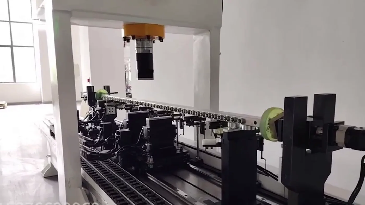
يجب أن تتصل نقاط الدعم بالأسطح العريضة المعتمدة. الموانئ, حبات اللحام, يتم تعريف الأسطح المانعة للتسرب والجدران الرقيقة غير المدعومة على أنها مناطق محمية. يتبع التحقق من صحة منطقة الاتصال نفس الشيء أدوات حماية السطح قواعد.
خطوة 2: رسم خريطة للتشوه الناجم عن اللحام
تحقيقات الاتصال, تقوم أجهزة استشعار الليزر أو مجموعة منها بقياس السطح المرجعي ذي الصلة في مواضع متعددة. تميز وحدة التحكم القوس العام عن التشوه المحلي بالقرب من اللحامات. إذا تم التحكم في الانحناء الرأسي والأفقي, يحتاج النظام إلى قياسات في كلا الاتجاهين أو تسلسل إعادة توجيه جزئي تم التحقق منه.
خطوة 3: حساب مواقف الصحافة والدعم
يحدد عنصر التحكم ذروة الانحناء ويحدد نقطة تصحيح آمنة بين المنافذ الحرجة. تصلب القسم المحلي, المسافة إلى أقرب اللحام ومدى الدعم تؤثر على السكتة الدماغية الأولية. يجب أن تتجنب الإستراتيجية الضغط ببساطة على أكبر انحراف يتم قياسه عندما يكون هذا الموقع منطقة ضعيفة أو وظيفية.
خطوة 4: تطبيق تصحيح الصحافة التي تسيطر عليها
تطبق الصحافة ضربة محدودة للانحناء الزائد للتعويض عن الزنبرك. تعمل الأدوات ذات الخطوط العريضة على توزيع الحمل عبر الأنبوب المستطيل. حيث يكون خطر انهيار الجدار مرتفعا, مغزل داخلي, قد تكون هناك حاجة إلى مواد حشو محلية أو دعم خارجي متخصص بعد المراجعة الهندسية.

ينبغي تطوير حدود القوة والإزاحة من عينات ملحومة تمثيلية. قد يشير التغيير المفاجئ في استجابة إزاحة القوة إلى دعم غير صحيح, نموذج جزء مختلف أو انهيار محلي ويجب أن يؤدي إلى إطلاق إنذار.
خطوة 5: إعادة قياس الحلقة المغلقة
بعد التصحيح, ويتم قياس المشعب على نفس المسند. يُسمح بالتصحيح الإضافي فقط ضمن حدود الدورة والحدود المعتمدة. إذا لم يتمكن الجزء من الوصول إلى الهدف دون المخاطرة بالمنفذ, اللحام أو تلف الجدار, يتم إرساله إلى NOK أو المراجعة الهندسية اليدوية.
خطوة 6: التفتيش النهائي والنقل
قد يشمل القبول النهائي الاستقامة/التسطيح, اتجاه النهاية, موقف الميناء, حالة السطح واختبار التسرب. يجب ألا يدعي جهاز تمليس الشعر أنه يتحقق من سلامة التسرب ما لم يتم تضمين محطة اختبار تسرب متكاملة بالفعل.
فحص القدرات ل 12,000 أجزاء في الشهر
يجب تحويل حجم الإنتاج إلى وقت عمل باستخدام أيام العمل الفعلية, التحولات, الساعات المتاحة واستخدام المعدات المستهدفة. على سبيل المثال, 12,000 لا يمكن للأجزاء شهريًا تحديد الدورة المطلوبة بمفردها حتى يتم معرفة عدد ساعات الإنتاج وما إذا كانت مرحلتي التصحيح مطلوبة لكل جزء.
تصحيح الالتواء اليدوي الحالي يبلغ حوالي 30 دقيقة لكل جزء توفر خط الأساس, ليست نتيجة آلة أوتوماتيكية. يجب أن يتضمن نموذج السعة الكاملة التحميل, قياس, تصحيح, إعادة القياس, التفريغ, التحول, فحص الأداة, التوقف المخطط له والنسبة المئوية للأجزاء التي تحتاج إلى دورات إضافية.
| مدخلات السعة | القيمة المطلوبة |
|---|---|
| الكمية الشهرية | 12,000 أجزاء |
| أيام العمل/الشهر | العميل للتأكيد |
| التحولات / اليوم والساعات / التحول | العميل للتأكيد |
| الهدف OEE / استخدام | العميل للتأكيد |
| النسبة المئوية التي تتطلب تصحيح الالتواء قبل اللحام | ليتم قياسها |
| النسبة المئوية التي تتطلب تصحيح الانحناء بعد اللحام | ليتم قياسها |
| متوسط / دورات التصحيح القصوى | نتيجة اختبار العينة مطلوبة |
| مطلوب عازلة بين اللحام والاستقامة | قرار تخطيط الخط |
تكوين الخلية المقترح
| الوحدة النمطية | التكوين المقترح |
|---|---|
| محطة ما قبل اللحام | لقط الملف الشخصي, قياس الزاوي/الالتواء والتحكم في الدوران المضاد |
| محطة ما بعد اللحام | مكواة فرد الشعر ذات السرير الطويل مع دعامات موزعة قابلة للتعديل |
| نظام القياس | قياس الزاوي/مسند النهاية بالإضافة إلى استشعار الإزاحة الخطية متعددة النقاط |
| الأدوات | اتصال احيط واسعة ل 78 × 45 × 3 مم مقطع مجوف |
| الضغط | رأس ضغط متحرك أو مفهرس مع حدود القوة/الإزاحة |
| المناولة | المساعدة اليدوية, جسر الرافعة أو الروبوت وفقًا لوزن الجزء والمهارة |
| الضوابط | وصفات منفصلة قبل اللحام وبعد اللحام, تصحيح الحلقة المغلقة ومنطق OK/NOK |
| بيانات | تطور واردة / النهائي والانحناء, عدد التصحيح, الوصفة ومعرف الجزء كما هو مطلوب |
| أمان | حراسة متشابكة, الحماية من الحمل الزائد واستراتيجية الكشف عن الانهيار غير الطبيعي |
خطة التحقق من صحة المشروع
يجب أن تتضمن العينات التمثيلية الالتواء الوارد العادي والحد الأقصى, مجموعات لحام مختلفة وأكبر تشوه متوقع بعد اللحام. يجب أن يتحقق الاختبار مما إذا كان 3 يمكن تصحيح الملف الشخصي مم دون المسافة البادئة, تلف المنفذ, تكسير اللحام أو الإجهاد المتبقي غير المقبول.
يجب أن يشير تقرير القبول بوضوح إلى متطلبات العملاء, نتائج اختبار العينة ونتائج الإنتاج اللاحقة. وينبغي أيضا أن تحدد ما إذا كان 0.15 مم يمكن تحقيقه وذات مغزى للكامل 1800 مم متعددة, نطاق المرجع المحلي, سطح الختم, موضع المنفذ أو خاصية رسم أخرى.
المعلومات اللازمة لاقتراح مشعب التبريد السائل
يرجى تقديم الرسم الكامل وGD&ت, 3نموذج د, شهادة المواد, تسلسل اللحام, وزن الجزء, تعريف تطور الواردة والتوزيع, خريطة تشوه ما بعد اللحام, التسامح النهائي والمسند, الأسطح المحمية, مناطق المشبك/الدعم/الضغط المسموح بها, معايير التسرب والسطح المطلوبة, تقويم العمل, المعدل المستهدف, تخطيط الخط وعينات تمثيلية قبل اللحام وبعده.
تحدد هذه المدخلات ما إذا كان المشروع يحتاج إلى جهازين مستقلين, خلية مجتمعة, محاور تصحيح متعددة, دعم الأنبوب الداخلي, التعامل الآلي أو مقياس المصب.
التعليمات
يمكن لآلة واحدة تصحيح كل من الالتواء والانحناء?
من الممكن دمج عدة محاور في خلية واحدة مخصصة, لكن الالتواء والانحناء لا يزال يتطلب قياسات وإجراءات تصحيح مختلفة. غالبًا ما تكون المحطات المنفصلة أكثر وضوحًا وأسهل في التحقق من صحتها بالنسبة لخط عالي الحجم.
لماذا لا يكفي الضغط العمودي البسيط للإبلاغ 20 ملم تطور?
الضغط العمودي يصحح الانحناء في المقام الأول. يتطلب الالتواء دورانًا نسبيًا متحكمًا فيه لنهايات المظهر الجانبي أو آلية التواء أخرى تم التحقق منها مع ردود فعل زاويّة.
كيف هو 3 ملم جدار من الفولاذ المقاوم للصدأ محمي?
يستخدم التثبيت والصحافة اتصالًا محيطيًا واسعًا على الأسطح المعتمدة, مع حدود القوة / السكتة الدماغية المحافظة. قد يكون الدعم الداخلي مطلوبًا عندما تكون مخاطر الانهيار المحلية عالية.
يمكن أن يحقق الخط 0.15 دقة مم?
تحتاج القيمة أولاً إلى تعريف رسم ومسند. تعتمد إمكانية الإنجاز بعد ذلك على الهندسة الكاملة, توزيع اللحام, الاستجابة المادية, طريقة القياس ونتائج اختبار العينة.
يمكن التعامل مع هذه العملية 12,000 متعددة شهريا?
يجب تحويل الحجم الشهري إلى وقت العمل باستخدام أيام العمل, التحولات, OEE والنسبة المئوية للأجزاء التي تتطلب كل مرحلة تصحيح. يتم تأكيد السعة فقط بعد توفر بيانات دورة العينة.
هل يظهر الفيديو الحل الكامل على مرحلتين?
لا. إنه يُظهر محطة تسوية الضغط ذات المشعب الطويل. لم يتم إثبات معدات تصحيح الالتواء المنفصلة قبل اللحام الموصوفة في الحل المقترح بواسطة هذا الفيديو.
خاتمة
تتطلب مشعبات التبريد السائل أكثر من مجرد مكبس استقامة عام. يمكن أن يكون للأنبوب المستطيل الوارد خطأ التوائي, اللحام يخلق تشوه الانحناء الثاني, ويجب تصحيح القسم المجوف الرقيق 304L دون سحق المنافذ, اللحامات أو واجهات الختم.
لتحويل توجيه مشعب التبريد السائل هذا إلى قرار شراء, ابدأ بـ تجول اختيار مستقيم واختبار الضغط على الأرقام باستخدام صورة الميزانية لآلة استقامة.
إرسال الرسم المتنوع, تعريف تطور, تسلسل اللحام, بيانات تشوه ما بعد اللحام, مسند الهدف, تقويم الإنتاج الشهري والعينات التمثيلية. يمكننا بعد ذلك تصميم وتصنيع حل استقامة انحناء ما قبل اللحام وثني ما بعد اللحام حول قطعة العمل الفعلية ومتطلبات المهارة.